
Related Manuals for AnaPico APPH6040


Summary of Contents for AnaPico APPH6040
- Page 1 User’s Manual 2.2 (March 2014) APPH Models APPH6040, APPH20G, APPH6000 -IS400 Anapico AG Europastr. 9 CH-8152 Glattbrugg Switzerland Tel: +41 44 515 5501 www..anapico.com...
- Page 2 All Anapico instruments are warranted against defects in material and workmanship for a period of two years from the date of shipment. Anapico will, at its option, repair or replace products that prove to be defective during the warranty period, provided they are returned to Anapico and provided the preventative maintenance procedures are followed.
-
Page 3: Table Of Contents
Connecting through USB to APPH GUI ..................11 2.4.5 Connecting through USBTMC & VISA .................... 11 2.4.6 Connecting through GPIB & VISA ....................12 2.4.7 Using Anapico Application Programming Interface (API).............. 12 2.4.8 Installing the APPH Graphical User Interface Software ..............12 2.4.9 Troubleshooting ..........................12 2.4.10 Shutting Down the APPH ...................... - Page 4 MAINTENANCE AND WARRANTY INFORMATION .................. 50 ........................50 DJUSTMENTS AND ALIBRATION ..............................50 EPAIR LAN ......................50 PGRADING THE IRMWARE VIA ..............................50 AFETY ..........................51 ARRANTY NFORMATION ..........................51 QUIPMENT ETURNS Anapico AG Europastr. 9 CH-8152 Glattbrugg Switzerland Tel: +41 44 515 5501 www..anapico.com...
-
Page 5: Introduction To The Apph
APPH. 1.1 General Features and Functions The different APPH models offer different measurement capabilities as shown in the table below: Model APPH6000-IS400 APPH6040 APPH20G RF frequency 5 MHz to 400 5 MHz to 7 GHz... -
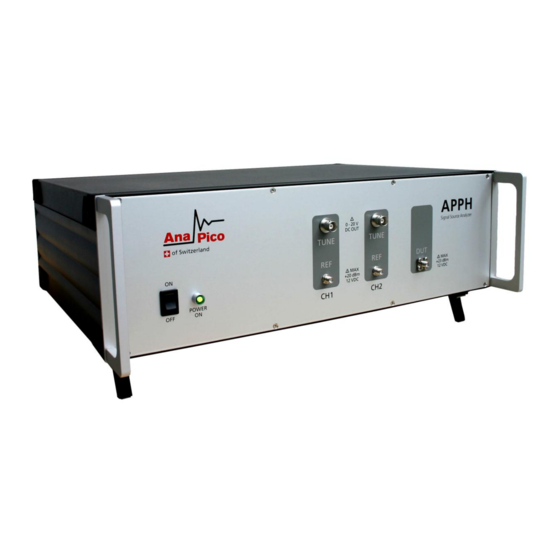
Page 6: Front Panel Overview
(APPH6000 ONLY) This female SMA connector is the reference LO output. The impedance is 50 ohm. In standard operation with internal references the REF OUT is connected by a short semi-rigid cable to the REF IN. Anapico AG Europastr. 9 CH-8152 Glattbrugg... - Page 7 Connect the measurement sample (DUT) to the port (or the test fixture, cables, etc. connected to the port) after discharging DUT's electricity enough. Anapico AG Europastr. 9 CH-8152 Glattbrugg Switzerland Tel: +41 44 515 5501 www..anapico.com...
-
Page 8: Rear Panel Connections
This female BNC connector is the programmable low-noise DC supply voltage output. APPH6000: Output voltage range is 0 V to +5 V, maximum available current is 80 mA. APPH6040/20G: Output voltage range is 0 V to +15 V, maximum available current is 500 mA. - Page 9 This GPIB connector is used only for controlling the APPH-IS from an external controller. You cannot control other devices from the APPH through this GPIB connector. Serial Number Plate The seal showing the serial number of the product. Anapico AG Europastr. 9 CH-8152 Glattbrugg Switzerland Tel: +41 44 515 5501 www..anapico.com...
-
Page 10: Getting Started
2.4.2 Connecting to LAN via DHCP Router Connect the APPH to your local area network (LAN) using the provided Ethernet cable. The instrument is configured to accept its dynamic IP number from the DHCP server of your network. If Anapico AG Europastr. 9 CH-8152 Glattbrugg... -
Page 11: Connecting Via Lan Without Dhcp Router (Fallback Or Fixed Ip)
GUI installation process that can be started from the provided installation CD or can be downloaded from the Anapico website. If installed properly, the Windows operating system will automatically detect the APPH as a USBTMC device and the APPH GUI will list it in its connection dialog. -
Page 12: Connecting Through Gpib & Visa
To install the GUI on the computer, insert the APPH Software and Manual CD into the CD/DVD drive or download the latest GUI setup file from the Anapico website. If the setup doesn’t start automatically double click on the setup.exe to run the auto-installer. -
Page 13: Shutting Down The Apph
Exceptions and then add Program. If the APPH Software is in this list choose it and click OK otherwise you have to browse for the path to AnaPico Software. Finally close all open dialogs with OK. Now your Windows™ Firewall is ready for APPH. -
Page 14: Measurement Using The Graphical User Interface (Gui)
3 Measurement using the Graphical User Interface (GUI) Anapico’s graphical user interface provides an intuitive control of the APPH. It runs under any operating system supporting a Java Runtime Environment (JRE). Make sure the software is installed and the computer’s firewall configured as required. -
Page 15: Organization Of The Gui
File Setting (Save, Load, Reset) allows storage and restoring of user defined parameter and measurement settings. When the GUI exits, the current configuration is automatically saved and restored at the next restart. File Exit will terminate the APPH GUI software. Anapico AG Europastr. 9 CH-8152 Glattbrugg Switzerland Tel: +41 44 515 5501 www..anapico.com... - Page 16 (.tar). After selecting a correct firmware file, the update takes about 30 seconds. The GUI will disconnect from the instrument during the update process. Device Info provides product details of the instrument such as firmware version, instrument serial number and options installed as shown below. Anapico AG Europastr. 9 CH-8152 Glattbrugg Switzerland Tel: +41 44 515 5501 www..anapico.com...
- Page 17 Plot Save Report auto-generates a pdf report including measurement trace, jitter data, Allan Dev plot and phase noise, spurious and marker data of the current measurement. Plot Clear Trace deletes the active measurement trace. Same function Plot Clear Shadow Anapico AG Europastr. 9 CH-8152 Glattbrugg Switzerland Tel: +41 44 515 5501 www..anapico.com...
- Page 18 Only spurious signals above the user set level will be displayed. The “Smoothing Aperture” setting can be used to video average the traces over a user set bandwidth. Anapico AG Europastr. 9 CH-8152 Glattbrugg...
- Page 19 View Toggle Fullscreen allows toggling from and to full screen mode. Help Activate Extended Mode is intended for AnaPico engineers only and is used to calibrate the devices. Currently, customers can not activate this option. Anapico AG Europastr. 9...
- Page 20 Help Activate Logging logs status and error information from the GUI into a binary file. This file can then be sent as part of an error report to the Anapico support email hotline. This should not be activated during normal use as the logging slows down the application which can affect the user experience.
-
Page 21: Measurement Tabs
Absolute Phase Noise, Additive Phase Noise, Amplitude Noise (APPH6000 only), Time Domain Analyzer (APPH20G and APPH6040 only), FFT Analyzer. Clicking on a tab will lead to the corresponding measurement setup. The following sections describe each measurement tab and how to configure it to successfully perform a measurement. -
Page 22: Phase Noise Measurement Tab
Disabling allows manual entry of the DUT frequency. Internal counters and power detector is shut down. Per default, the auto-detection is on and once a valid signal is detected, the Measure button turns green and is enabled. Anapico AG Europastr. 9 CH-8152 Glattbrugg... - Page 23 F) Click Measure Button: Once the Measure Button becomes green, a new measurement can be started. Click on the button to start the measurement and click again to stop the measurement before completion. Anapico AG Europastr. 9 CH-8152 Glattbrugg Switzerland Tel: +41 44 515 5501 www..anapico.com...
- Page 24 Once the measurement is completed, the GUI returns into idle state. During the idle state, the “beat” signal of the two measurement channels can be observed in the “Time Domain” tab of the measurement window as shown in Figure 9. Anapico AG Europastr. 9 CH-8152 Glattbrugg...
- Page 25 If the measurement trace at a given offset is above the noise floor the measured trace has reached a steady-state value at the same offset. Increasing number of correlation will only “smooth” the curve and remove trace noise, but will not further improve the phase noise value. Anapico AG Europastr. 9 CH-8152 Glattbrugg...
-
Page 26: Using External References
C) If your reference source does not provide sufficient output power, you can also use internal buffer amplifiers by clicking the “Buffer” checkbox. The buffer amplifier provides about 10 dB gain with a noise figure of 2 dB. Anapico AG Europastr. 9 CH-8152 Glattbrugg... -
Page 27: The Different Plot Window Tabs
The Time Domain tab is used to provide time domain measurement information during idle state (frequency and power detection, calibration) and during the measurement process (locking, and data acquisition). During the actual measurement, samples of the noise voltage are also displayed in this window. Anapico AG Europastr. 9 CH-8152 Glattbrugg Switzerland Tel: +41 44 515 5501 www..anapico.com... - Page 28 The values are updated approx. once per second in GUI idle state. The Measurement Status tab prints status and error messages that help user to verify the measurement process. Anapico AG Europastr. 9 CH-8152 Glattbrugg Switzerland Tel: +41 44 515 5501 www..anapico.com...
-
Page 29: The Traces Window
Individual trace colors can be assigned to traces by clicking on the color box on the right and selecting the desired color from the color dialog. Traces stored in the list can be made invisible in the current plot window by un-checking the checkbox in the left. Anapico AG Europastr. 9 CH-8152 Glattbrugg... - Page 30 1. Completely remove or show detected spurious signals that are above a user set threshold. 2. Apply video averaging (smoothing) to the trace with user set aperture. 3. Shift trace by a user specified number of decibels (up or down). Anapico AG Europastr. 9 CH-8152 Glattbrugg...
- Page 31 If enabled, Spur and Marker Lists, the RMS Jitter, Residual phase error, the residual FM and the integral phase noise are displayed for the selected trace in small windows inside the measurement window and offset range as shown in Figure 12. Anapico AG Europastr. 9 CH-8152 Glattbrugg...
-
Page 32: The Marker Window
“New” button as shown below and move the mouse within the plot window. The marker will follow the active or selected trace. You can move markers to the desired trace by selecting the corresponding trace in the trace list. Anapico AG Europastr. 9 CH-8152 Glattbrugg... -
Page 33: Inside Plot Window Functions
Print, Save and Copy Traces Phase noise plots can be printed by moving the mouse over the plot window and pressing the right mouse button (Figure 14) or through the Plot Print menu. Anapico AG Europastr. 9 CH-8152 Glattbrugg... -
Page 34: Saving Traces
All traces in an APPH internal format; the internal file format can be loaded into the GUI 3.4.8 Oversampling factor (APPH6000 / APPH30G only) Only for APPH6000 and APPH30G systems, the “More” button opens the Advanced Measurement Configuration Window with additional settable parameters as shown below: Anapico AG Europastr. 9 CH-8152 Glattbrugg Switzerland Tel: +41 44 515 5501 www..anapico.com... - Page 35 A higher oversampling factor gives better frequency resolution in the FFT and allows analyzing more details of spurious response. Additionally, individual number of correlations can be set for the measurement decades using the sliders on the left. Anapico AG Europastr. 9 CH-8152 Glattbrugg Switzerland Tel: +41 44 515 5501 www..anapico.com...
-
Page 36: General Measurement Settings
3.5.1 Number of data points per trace Per default, the number of points displayed in every trace is depending on the start and stop offset frequency. Data for APPH6000 / APPH30G and APPH6040 /APPH20G are shown in Table 1 and 2. Start / Stop... - Page 37 Table 3. Start Frequency Measurement Time Measurement Time (Hz) (sec) (sec) APPH6000 / 30G APPH6040 / 20G 0.1 Hz 1 Hz 10 Hz 100 Hz 1 kHz 10 kHz Table 3: Typical measurement time (sec) for APPH Anapico AG Europastr.
-
Page 38: Am Noise Measurement (Apph6000 Only)
Amplitude measurement does not require any reference sources and any few parameters must be set such as offset range and number of correlations. The amplitude noise measurement tab is shown in Figure 15. Figure 15 Amplitude noise tab Anapico AG Europastr. 9 CH-8152 Glattbrugg Switzerland Tel: +41 44 515 5501 www..anapico.com... -
Page 39: Additive Phase Noise Measurement
Next, select what kind of external phase shifter is deployed. Any phase shifter is suitable that does not excessively contribute own noise such as digital or mechanically tuned models. Models that are tuned via analog voltage can be supported by the APPH GUI. Anapico AG Europastr. 9 CH-8152 Glattbrugg... - Page 40 If already known for a given setup, the phase detector constant can be manually entered. In case “Analog Tune” is selected and voltage controlled phase shifters are used, this step is performed automatically by the instrument and can be omitted. Anapico AG Europastr. 9 CH-8152 Glattbrugg Switzerland Tel: +41 44 515 5501 www..anapico.com...
- Page 41 Figure 18. Measurement can be stopped and restarted without need of performing step 1 and 2 each time. Figure 17 Additive phase noise measurement tab (Time Domain) during step 2, automatically adjusting the phase to quadrature. Anapico AG Europastr. 9 CH-8152 Glattbrugg Switzerland Tel: +41 44 515 5501 www..anapico.com...
- Page 42 Figure 18 Additive phase noise measurement tab after the measurement completed. Anapico AG Europastr. 9 CH-8152 Glattbrugg Switzerland Tel: +41 44 515 5501 www..anapico.com...
-
Page 43: Transient Analyzer Measurement
3.8 Transient Analyzer Measurement Transient analyzer measurement is not yet supported. Please contact support@anapico.com to check availability. Anapico AG Europastr. 9 CH-8152 Glattbrugg Switzerland Tel: +41 44 515 5501 www..anapico.com... -
Page 44: Fft Analyzer Measurement
This tab is used to measure noise on one or two channels of the FFT analyzer. Select the frequency range and the number of averages. Under “More” select either “Single Channel” or “Two channel cross-correlated” measurement. Press start button to run measurement. Figure 19 FFT Analyzer Mode Anapico AG Europastr. 9 CH-8152 Glattbrugg Switzerland Tel: +41 44 515 5501 www..anapico.com... -
Page 45: System Calibration (Firmware 1.0 And Up)
This chapter describes the correction method and how to set up the calibration procedure. User calibration procedure will be supported from firmware and remote client revision 1.0 Please contact support@anapico.com to check availability. Anapico AG Europastr. 9 CH-8152 Glattbrugg... - Page 46 Anapico AG Europastr. 9 CH-8152 Glattbrugg Switzerland Tel: +41 44 515 5501 www..anapico.com...
-
Page 47: Remote Programming The Apph
The program is used to configure the LAN client. Once the computer is configured for a LAN client, you can use the VXI- 11 protocol and the VISA library to send SCPI commands to the signal generator over the LAN interface. Example programs are available on request under support@anapico.com. Anapico AG Europastr. 9 CH-8152 Glattbrugg Switzerland Tel: +41 44 515 5501 www..anapico.com... -
Page 48: Using The Usb-Tmc Interface With Visa
When controlling the APPH using GPIB commands from the external controller connected to the GPIB connector, you need to set the talker/listener GPIB address of the APPH. Please see the APPH Programmer’s Manual for further details. Anapico AG Europastr. 9 CH-8152 Glattbrugg... -
Page 49: Type And Structure Of Commands
For the commands in this group, there is no hierarchical structure. 6.1.2 Using SCPI for APPH Anapico instrument are message based, which means they are controlled through text commands, typically following the SCPI standard which is vendor-independent and interface-independent. Anapico devices offer several I/O options use the same SCPI commands through all these interfaces, especially LAN and USB. -
Page 50: Maintenance And Warranty Information
It is recommended to regularly check for new firmware for the APPH. If new firmware is available, it can be downloaded from the Anapico website and locally stored. Then, it can be uploaded directly to the instrument via Device Upload Firmware 7.4 Safety... -
Page 51: Warranty Information
All AnaPico instruments are warranted against defects in material and workmanship for a period of two years from the date of shipment. AnaPico will, at its option, repair or replace products that prove to be defective during the warranty period, provided they are returned to AnaPico and provided the preventative maintenance procedures are followed.
Need help?
Do you have a question about the APPH6040 and is the answer not in the manual?
Questions and answers