Table of Contents
Advertisement
Quick Links
8 Channel Video Receive Unit with 1 Bi-directional Data
Channel plus Ethernet and Dual Redundant Operation -
includes AMG NMS Network Management Interface
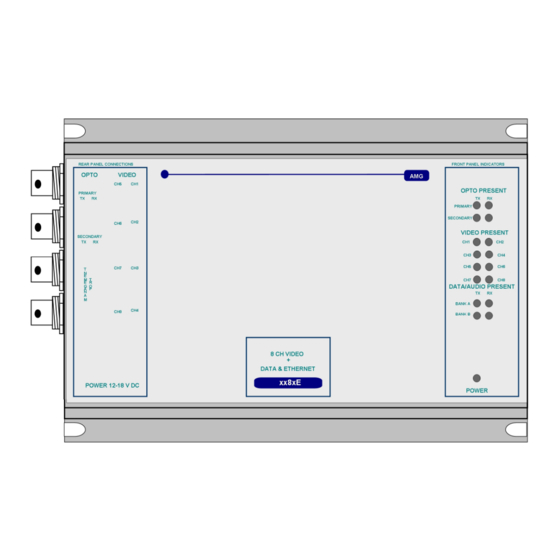
The AMG4784EN-DR-SF is a standalone eight channel video receive unit designed to receive 8 video
signals and transmit and receive 1 data signal plus full duplex 100BaseT Ethernet connectivity over
one singlemode fibre with Dual Redundant operation. It also includes an AMG Management Interface
to allow Management of the system using the AMG SNMP enabled Management software.
The AMG4784EN-DR-SF is designed to be powered using an AMG2003 standalone power supply.
The AMG4784EN-DR-SF is designed to operate with AMG4783E-DR-SF or rackmount equivalent
AMG4783ER-DR-SF eight channel video transmit unit in a point to point configuration.
AMG Systems Ltd. reserves the right to make changes to this
document without notice. The information herein is believed to
be accurate. No responsibility is assumed by AMG for its use.
AMG4784EN-DR-SF
Instruction Manual
Page 1 of 12
AMG4784EN-DR-SF Instruction Sheet
D16829-02.doc
Advertisement
Table of Contents

Related Manuals for AMG AMG4784EN-DR-SF


Summary of Contents for AMG AMG4784EN-DR-SF
- Page 1 Channel plus Ethernet and Dual Redundant Operation - includes AMG NMS Network Management Interface The AMG4784EN-DR-SF is a standalone eight channel video receive unit designed to receive 8 video signals and transmit and receive 1 data signal plus full duplex 100BaseT Ethernet connectivity over one singlemode fibre with Dual Redundant operation.
-
Page 2: Table Of Contents
Removal / replacement from / to the Case..................10 Safety Maintenance and Repair AMG Systems Ltd. reserves the right to make changes to this Page 2 of 12 AMG4784EN-DR-SF Instruction Sheet document without notice. The information herein is believed to D16829-02.doc... -
Page 3: Introduction
The secondary optical input is independent and is regenerated on the secondary output. At the AMG4784EN-DR-SF receiver if the primary input signal is not present, the unit will shut down the secondary output to inform the AMG4783E-DR-SF that the primary signal route is not OK. The AMG4783E-DR-SF will then send out the video and data signals on its secondary output in the opposite direction. -
Page 4: Connections
RS485 – switch position – low (furthest from BNC connections) DATA CHANNEL B Data Channel B ........Not Present AMG Systems Ltd. reserves the right to make changes to this Page 4 of 12 AMG4784EN-DR-SF Instruction Sheet document without notice. The information herein is believed to D16829-02.doc... -
Page 5: Data And Audio Channel Configuration
RS485 bus high (+5 volts) and the other arm low (0 volts) using high value resistors within the third party equipment. In order to ensure that the AMG equipment detects a tri-state condition, then these resistors should have a value above 5kΩ. If the third party bias resistors are less the 750Ω... -
Page 6: Front Panel Indicators
OUT+ logic one (-V) present on OUT+ This represents the data signals being received on the optical fibre AMG Systems Ltd. reserves the right to make changes to this Page 6 of 12 AMG4784EN-DR-SF Instruction Sheet document without notice. -
Page 7: Network Management
Power at the receiver Closed by: Reset The Management Interface The Management Interface is fitted to AMG receivers / transmitters and is signified by a 'N' in the part number AMG Systems Ltd. reserves the right to make changes to this... - Page 8 Each management interface, thus each receiver or transmitter, has an ID number with is identified below the management port. This ID number is used by the AMG Network Management System (NMS) to identify the unit. The physical interface is a 9 way female D-type connector. It supports either RS-232 or RS-485.
-
Page 9: Alarm Output And Reset Operation
On release of the alarm reset, the alarm output will remain in a closed state until the next change of state to the AMG transmit unit connected to the receiver. The alarm output may not register a change of state which happens within 5 seconds of release of the alarm reset. -
Page 10: Physical Information
Mounting Details The AMG unit is supplied with a clip-on mounting bracket which should be attached to a panel or wall using 2 off 4.0mm screws. The unit is clipped into the mounting bracket, and is then held firmly in position. - Page 11 This page is intentionally blank. AMG Systems Ltd. reserves the right to make changes to this Page 11 of 12 AMG4784EN-DR-SF Instruction Sheet document without notice. The information herein is believed to D16829-02.doc be accurate. No responsibility is assumed by AMG for its use.
- Page 12 This page is intentionally blank. AMG Systems Ltd. reserves the right to make changes to this Page 12 of 12 AMG4784EN-DR-SF Instruction Sheet document without notice. The information herein is believed to D16829-02.doc be accurate. No responsibility is assumed by AMG for its use.
Need help?
Do you have a question about the AMG4784EN-DR-SF and is the answer not in the manual?
Questions and answers