
Subscribe to Our Youtube Channel
Related Manuals for Arlyn Scales 3250 Series


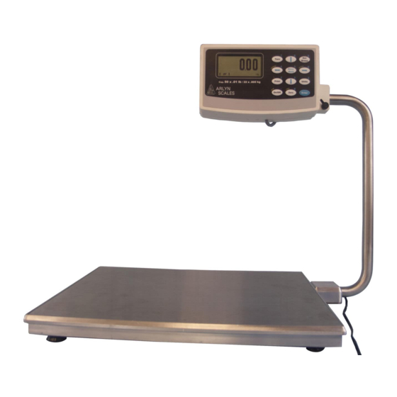
Summary of Contents for Arlyn Scales 3250 Series
- Page 1 Digital Scales 3200, 3250, 6200 & 5-XXXX Series Equipped with MKE-5 Display Indicator User Manual 59 Second Street East Rockaway, NY 11518 (800) 645-4301 www.arlynscales.com v12.0.041823...
-
Page 2: Table Of Contents
CONTENTS CONTENTS ......................................2 1 YOUR NEW SCALE ....................................5 1.1 S ....................................5 CALE ERSION 1.2 A ..................................5 DDITIONAL ANUALS 1.3 F ...................................... 5 EATURES 1.4 P ....................................5 RECAUTIONS 1.5 B ............................... 5 ONDITIONS FOR EIGHING 1.6 I ................................ - Page 3 4.1.9 Zero / Motion Detect ................................15 4.1.10 Multi-Platform Settings (for Multiple Platform Configurations Only) .................. 16 4.1.11 Adjust Zero Offset ................................16 4.1.12 View Raw ADC Data ................................16 5 CALIBRATION AND TROUBLESHOOTING ............................16 5.1 S .............................. 17 CALE READS ZERO AND WILL NOT MOVE 5.2 S .
- Page 4 11.2.2 Creating and Editing Formulas ............................33 11.2.3 Notes on Cycle Mode ................................ 34 11.2.4 Output Connector and Pin Diagram ........................... 35 12 WEIGHT AVERAGING ..................................35 12.1 P ................................35 UTTON PERATION 12.1.1 For Multiple Platforms ..............................35 12.2 C ................................
-
Page 5: Your New Scale
1 YOUR NEW SCALE Congratulations on your purchase of an Arlyn Digital Scale. This Scale offers a combination of versatility, accuracy and simplicity in an easy to use and easy to maintain package. Advanced menu driven operating software, large memory capacity and an easy to use menu structure allows the scale to be configured for almost any application. -
Page 6: Initial Set-Up And Operation
2. Best operating temperature is about 68 degrees F. 3. The weighing area should be kept clean and dry. 4. The surface that the scale is resting on should be of solid construction and not prone to vibrations. 5. Don’t install the scale near heater or air conditioner vents. 6. -
Page 7: Front Panel / Keyboard
WEIGHT DISPLAY Shows the weight on the platform in the current units setting. COUNT DISPLAY Shows the current piece count on the platform. If there are any totals in the accumulate register it will indicate “pcs acc” UNITS Shows the active conversion units. NET INDICATOR Shows “Net”... -
Page 8: Menu Navigation Keys
TARE Tares any weight on the platform and switch the scale to the net mode. Hold the key down to clear the tare NET/GROSS Will toggle the indicator between the net and gross mode. The net mode will show the weight on the platform minus any tared weight. -
Page 9: Tare Definitions
The TARE key can also allow you to quickly specify a weight that you want to tare out without going through the Tare Definitions process. To set this function, please look at the Tare Button Function below. Tares can also be taken, named, activated and stored permanently through the setup menu. Go to menu SETUP MENU/TARES. A list of options is displayed on the screen: Tare Definitions Create a record of predefined tares that can for pre-existing weights of containers. -
Page 10: Tare Button Function
3.2.2.2 Analog Enabled (For Analog Output “4-20ma” equipped scales only) By default, if the user tares a weight from the platform (and the screen shows zero weight), the analog output will continue to detect the gross weight even if the screen shows zero, and therefore continues to produce the analog equivalent of the gross weight. Selecting this option to “Yes”... -
Page 11: Restore
3.4.2 Restore Use this function to restore a backup of a previous scale configuration. This is helpful if you already created a backup of your previous working configuration. Use this function and follow the prompts on screen to restore of your scale to a previous backed up configuration. -
Page 12: Revision Number
3.4.11 Revision Number This option reads out the current operating system revision number. 3.4.12 Auto Shut-Off Auto Shut-Off allows you to set your scale to automatically shut off when a preset time limit has been reached and there has been no activity on the scale. -
Page 13: Span Calibration
4.1.3 Span Calibration Span calibration adjusts the platform’s sensitivity so that the display reads correctly. A calibrated weight is required to perform this and the procedure is outlined below in the “Span Calibration” section. 4.1.4 Resolution-Overload This setting should not be touched unless instructed by a Service Technician. Each platform has the capability of displaying its reading in any of eight standard conversion units. -
Page 14: Software Filter
Tracking. After studying the scale’s behavior on this aspect, we can plug this 0.2lb range in this Window field. Now you will notice that your scale will zero out any deviations that falls within ±0.2lbs. Noise Count – NCNT: This is the noise count of filtering mechanism. This sets the number of weight values that need to be discarded before considering that the new weight value is a new value and not part of the current weight value tracking process. -
Page 15: Zero / Motion Detect
Active – ACTV: Activates or deactivates Stability Control. Source – SRC: This sets the primary source of readings that the Stability Control mechanism will use to estimate the best lock-in weight. There are two selections here: A/D Reading - This selection makes the Stability Control mechanism take readings unfiltered and straight from the load cell. ❑... -
Page 16: Multi-Platform Settings (For Multiple Platform Configurations Only)
4.1.10 Multi-Platform Settings (for Multiple Platform Configurations Only) This screen allows you to configure the scale to calculate the “Sum” or the “Difference” between the weights of two connected platforms. You can also configure the scale to automatically scroll through all platforms at specific intervals. This means that after a certain periodic interval, the scale will show the individual weight on each platform alternatively. -
Page 17: Scale Reads Zero And Will Not Move
5.1 Scale reads zero and will not move. Make sure that any and all shipping screws are removed from the platform. ❑ ❑ On platform scales, check that all four level legs are contacting solidly against the floor. If level legs are screwed in all the way then the stud from the level leg may be contacting the underside of the platform not ❑... -
Page 18: Platform Connector Pinout
5.6 Platform Connector Pinout *Please note that the pin numbers shown here are for convenience. The actual pin number on the connector as designated by its manufacturer is different and may vary. -
Page 19: Primary Menu Tree
6 PRIMARY MENU TREE Activate Description Edit Value Tare Defs. Acquire Next Screen Delete Tares Persistence Activate Description Tare Settings Analog Edit Value Setpoint Parts Counting Sample Defs. Acquire Delete Pounds Kilograms Edit Descr. Grams View Raw ADC Data Platform Setups Ounces Resolution Troy Ounces... - Page 20 Options Guide...
-
Page 21: Introduction To Options
7 INTRODUCTION TO OPTIONS This section will cover the operation and setup of all of the options available for your scale. It is important to note that some described menu items will be missing if that option was not installed in your specific scale. All of the options listed may be installed in any scale and may run concurrently. -
Page 22: Print Stream Mode
8.5 Print Stream Mode Print stream mode will continuously print the currently active print frame at fixed time intervals. Stream mode can be configured using menu SETUP MENU/OPTION SETUPS/RS232/PRINT STREAM. The lower menu selection ENB will enable or disable print stream mode, and TIME will be the number of seconds between the beginning of each print frame. -
Page 23: Print Stream Mode With Print-At-Stability
Zero Notify – ZERO NTFY: If this option is set to “YES”, then each time the scale is zeroed or a zero command is sent through one of the communication ports, the indicator will wait for the scale to stabilize and detect if there is no motion. Once these conditions are detected, the word “ZERO”... -
Page 24: Print Frame Functions
Allows you to print space(s) at the end of the current function. When activated a “?” will show up in the function list on the current line and allow you to enter a number. The number of spaces must be between 0 and 15. TEST Quickly test the print frame without having to return to the scale’s normal operating mode. -
Page 25: Text Definitions [Not Supported At This Time]
3. Line 5 shows the date followed by a carriage return and a line feed. 4. Line 6 will show the scale’s text description (as programmed through the system menu) followed by 3 spaces. 5. Line 7 shows the weight followed by a carriage return and a line feed. 6. -
Page 26: External Command Interface
Let Qual ESC x 0 <27 120 0> Select letter quality print Roman ESC k 0 <27 107 0> Select Roman font Sans Ser ESC k 1 <27 107 1> Select Sans Serif font Courier ESC k 2 <27 107 2> Select Courier font Prestige ESC k 3... -
Page 27: The [*] Command: Used For Keyboard Emulation
<descr> Any command that changes the contents of a memory slot will require a 14-character description. This description should exactly match the description of the item in question. The description must be 14 characters in length and spaces should be used for any unused characters just as they are used in the scale’s setup menus. -
Page 28: The [@] Command: Interactive Commands [Not Supported]
ACTIVATE (X) !SA <descr> <CR> CLEAR (X) !SC <CR> simply clears the active sample. ACQUIRE (X) !SQ <descr> <sample size> <CR> adds new sample and becomes interactive for acq 8.10.5.3 Print Frames NEW (5.021) !FN <descr> <CR> LINE EDIT (5.021] !FL<14 chr src descr>... -
Page 29: Test Using Terminal
this can be shut off to work with a 3-wire system. If not, you can wire the connector to “trick” the computer etc. to work properly. This involves shorting the RS232 RTS and CTS line together and shorting the DTR and DSR lines together. For 25-pin connectors short pins 4 and 5 for RTS/CTS and pins 6 and 20 for DTR/DSR. -
Page 30: Time And Date
9 TIME AND DATE When your scale is equipped with the time and date option you can get time and date and day of week readouts on the screen or use them in RS232/USB/Ethernet output frames. The time can be printed in either 12 or 24-hour format. Consult the section on Print Frame Functions for details. -
Page 31: Analog Setup Menu
10.2 Analog Setup Menu The analog setup menu can be found under menu SETUP MENU → OPTION SETUPS → ANALOG OUTPUT. Programmable parameters are as follows: Activate – ACTV - Will activate or deactivate the option. Start Current – START - The starting current that will correspond to zero on the display. End Current –... -
Page 32: Setpoint Controller
The “Total Weight” behavior is similar to what is described in the Single Channel Analog Output section above. Press the SHIFT + 6 key to enable “Total Weight” signal on Analog Output channel 1. Press SHIFT + 6 key again to revert back to multi-channel behavior. 11 SETPOINT CONTROLLER The setpoint controller gives your scale the capability to output a signal to external equipment when certain conditions are met. -
Page 33: Creating And Editing Formulas
Invert – INV=On/Off: If it is on then all outputs related to this setpoint will be inverted. This is useful when using the open collector output for the reasons stated earlier in this section. Cycle Mode – CYCLE=On/Off: The cycle option is used to create an operation cycle as described earlier in this section. Negative Reading –... -
Page 34: Notes On Cycle Mode
>= 5.00 < 5.00 // Now the “accept” (green light), to be on only between 5 and 5.2lb >= 5.00 > 5.20 <= 5.20 // Now the “over” (yellow) light to be on anytime the weight is above 5.2lb > 5.20 When this formula is executed, the scale evaluates each line in order. -
Page 35: Output Connector And Pin Diagram
11.2.4 Output Connector and Pin Diagram In most cases there will be a single cable with a 15-pin subminiature D type female connector added to the scale for interfacing to external equipment. SIGNAL Setpoint #4 Output Setpoint #5 Output Setpoint #6 Output Setpoint #7 Output Setpoint #8 Output Setpoint #3 Output... -
Page 36: Multiple Platform Operation
13 MULTIPLE PLATFORM OPERATION Your scale has the capability of displaying weights from up to three (3) platforms. There are only a few basic operational differences between a single platform configuration and a multiplatform configuration. Please see the figure below: 1. -
Page 37: Battery Pack Operation
8. If the multiple platform scale has options attached to it, such as RS232, USB, Analog Output, Setpoints, etc. make sure to read the special notes for that section, if any, that might apply specifically for multiple platform operation. 14 BATTERY PACK OPERATION The Battery Pack Option will allow the scale to be operated in areas where no power is available. -
Page 38: Note
8. Press the “On/Off” key again & your scale will be operational. 9. Only shut off toggle switch if you are not going to use the scale for a long period of time. 10. If the toggle switch is not on the “On” position the scale will not charge. 14.5.1 Note The scale will automatically shut off if the scale is not being used in 15 min (by default). -
Page 39: Adding A Reading To The Collection
To configure the memory, enter the new size through the setup screen. Size is the number of readings (maximum) that you would like to be able to store. This number will automatically be rounded up to the next multiplier of 8 (8 readings per slot). The memory is then set aside for data collection, and becomes invisible to the rest of the system. -
Page 40: Print Stream Mode
17.2 Print Stream Mode [Refer to Print Stream Mode in RS232 Chapter] 17.3 Print at Stability Using Motion Detection and Stability Control [Refer to Print at Stability in RS232 Chapter] 17.4 Print Frame The USB Print Frame configuration is shared with the RS232 Framework. Refer to Print Frame in RS232 Section. -
Page 41: Datalogging Print Frame
key in succession. Please make sure to see the “Shft” notification on the top left corner of the screen before pressing the ENTER key. The ENTER key may have to be held a half-a-second longer to register the “Recording Entry” notification. The SHIFT+ENTER key-sequence will have the same effect as the TWO-key described above in the Basic Operation section. -
Page 42: Ethernet (Tcp/Ip Socket)
UniTxt √ √ // Line #4, Units To change the frame to include more data types, you can refer to instructions outlined in the Print Frame section defined for RS232 Option. Please note that a frame is only saved when the user moves out of the Print Frame screen. If the scale is turned off while the user is still on this screen, the frame will be lost permanently. -
Page 43: Bluetooth 4.0 (Ble)
3. If you require an out-of-the-box datalogging software, you can take a look at commercial products such as WinWedge: http://www.taltech.com/products/winwedge.html. This software can pull data from many types of ports including Ethernet and you can do a lot more with your export data. For further help on integrating the Ethernet equipped scale to your framework, please refer to the documentation that came with the scale shipping package and the included CD. -
Page 45: Keyboard Wedge
This is especially troublesome if there are IT rules and limitations for installing software. Here at Arlyn Scales, we have solved these issues by providing an option to equip the scale to act as a keyboard wedge directly without the need to install complicated software. -
Page 46: Specifications
Multi-platform, Analog Output, Ethernet, Wireless Ethernet, USB Flash Data Logger 25 LIMITED WARRANTY Arlyn Scales warrants that your Arlyn Scales equipment and systems, when properly installed will operate per written specifications. All systems and components are warranted against defects in materials and workmanship for a period of one year. -
Page 47: Revision History
Arlyn Scales will, at their option, repair or replace such goods returned within the warranty period subject to the following conditions: Upon discovery by Buyer of such nonconformity, Arlyn Scales will be given prompt written notice with a detailed explanation of the alleged deficiencies.
Need help?
Do you have a question about the 3250 Series and is the answer not in the manual?
Questions and answers