Advertisement
Quick Links
Advertisement

Subscribe to Our Youtube Channel
Related Manuals for Halo PRIME550


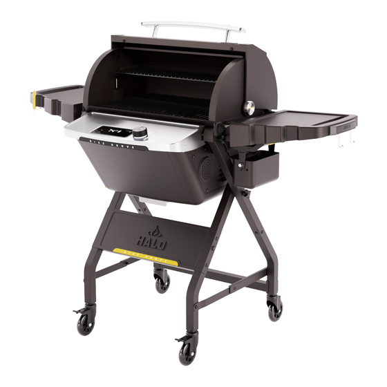
Summary of Contents for Halo PRIME550
- Page 1 TRILINGUAL ASSEMBLY STEPS AVAILABLE AT HALO-PG.COM HS-1001-XNA...
- Page 2 WARNING "Please read this entire manual before installation and use of this pellet-burning appliance. Failure to follow these instructions could result in property damage, bodily injury, or even death." WARNING The manufacturer has made every effort to eliminate any sharp edges. However, you should handle all components with care to avoid accidental injury.
- Page 3 IMPORTANT: Please read all instructions thoroughly before proceeding. Find a large, clean area in which to assemble your HALO Prime550 Pellet Grill. Please refer to the assembly diagram, as necessary. Install Left-Inner Leg using (3)-M6 x 14mm Screws and install leg cap.
- Page 4 Install Left-Outer Leg using (3)-M6 x 14mm Screws and install leg cap. ITEM PART DESCRIPTION QTY. Leg Cap Left-Outer Leg-Long Left-Outer Leg-Short M6 x 14mm Screw...
- Page 5 Install Left Outer Leg Assembly, Left Inner Leg assembly using pivot bracket 68 & 69A, (2)-M6 x 2.5H x 9.5D shoulder screw, (1)-M6 x 63mm Knob w/ Threaded Shaft and Nylon-Spacer. Tighten screws firmly. Set assembly aside. ITEM PART DESCRIPTION QTY.
- Page 6 Install Right-Inner Leg using (3)-M6 x 14 Screws and install leg cap. ITEM PART DESCRIPTION QTY. Leg Cap Right-Inner Leg-Long Right-Inner Leg-Short M6 x 14mm Screw...
- Page 7 Install Right-Outer Leg using (3)-M6 x 14 Screws and install leg cap. ITEM PART DESCRIPTION QTY. Leg Cap Right-Outer Leg-Long Right-Outer Leg-Short M6 x 14mm Screw...
- Page 8 Install Right Outer Leg Assembly, Right Inner Leg assembly using pivot bracket 69 & 69A, (2)-M6 x 2.5H x 9.5D shoulder screw, (1) x 63mm -Knob w/ Threaded Shaft and Nylon- Spacer. Tighten screws firmly. Set assembly aside. ITEM PART DESCRIPTION QTY.
- Page 9 Install Front Panel and Rear Brace assembly using (8)-M6 x 14mm screws. IMPORTANT: Do not tighten screws completely until all screws for that step have been installed. ITEM PART DESCRIPTION QTY. Rear Bracket Front Panel RISE ABOVE Logo Plate M6 x 14mm Screw...
- Page 10 Attach the Casters using M12 caster wrench. Mount Casters with Lock to front legs and Mount Swivel casters to rear legs. NOTE: You can lock the casters that have locks, allowing you to assemble the caster without using a caster wrench. ITEM PART DESCRIPTION QTY.
- Page 11 Attach Brackets-Leg Support-Left and right using 6-M6 x 12 Truss head screws. ITEM PART DESCRIPTION QTY. Bracket-Leg Support-Left Bracket-Leg Support-Right M6 x 12 mm Screw...
- Page 12 Turn the cart right up with front casters still in locked position. Attach fire chamber assembly to the “X“ frame using (4) ¼”-20-Knob with Threaded Shaft to secure the cooking chamber in place. NOTE: We recommend the help of a friend to attach the fire chamber assembly onto the “X” cart frame due to the size and weight.
- Page 13 Install cooking grid and warming rack. ITEM PART DESCRIPTION QTY. Warming Rack Cooking Grid...
- Page 14 Warming rack continued. Warming rack is in usual position. Step1. Slide warming forward until center support wire is pushed against front section of the bracket. Step2. Left up warming then hook on to the “J” brackets.
- Page 15 Install side table brackets left and right using (12)-M6 x 14mm screws. Install side table left and right using (4)-M6 x 2.5H x 9.5D-Shoulder Screw. ITEM PART DESCRIPTION QTY. Bracket-Side Table-A Bracket-Side Table-B Release Spring Pin-Side Table/Cleanout Tray Side Table-Right Side Table-Left "JJ"...
- Page 16 1. Install ash tray by pulling the release spring pin, then insert the tray into the tray tracks and slide the tray all the way back. Release the spring pin to lock in place. 2. Insert the leveler into the housing.
-
Page 17: Part Description
Install grease cup with cover. ITEM PART DESCRIPTION QTY. Grease Bucket w/ Cover...
Need help?
Do you have a question about the PRIME550 and is the answer not in the manual?
Questions and answers