Advertisement
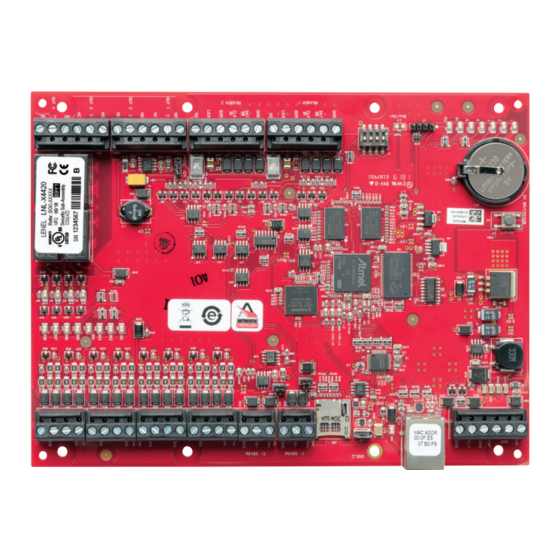
Intelligent Controller LNL-X4420 with Two Reader
Interfaces Quick Reference
General
The LNL-X4420 intelligent controller provides decision making, event reporting, and database storage for the Lenel
hardware platform. Two reader interfaces provide control for two doors.
The LNL-X4420 communicates with the host via on-board 10Base T/100Base-TX Ethernet port or the Micro USB
port (2.0) with an optional Micro USB to Ethernet adapter.
Two physical barriers can be controlled with the LNL-X4420. Each reader port can accommodate a read-head that
utilizes TTL (D1/D0, Clock/Data), F/2F or 2-wire RS-485 electrical signaling (OSDP reader for example) and also
provides tri-state LED control and buzzer control (one wire LED mode only). Four Form-C relay outputs may be
used for door strike control or alarm signaling. Eight inputs are provided for monitoring the door contacts, exit push
buttons, and alarm contacts. Input circuits can be configured as unsupervised or supervised. The LNL-X4420 requires
12 to 24 VDC for power.
LNL-X4420 Hardware
Battery: BR/CR2330
(replace annually)
0.25 [6.35]
0.50 [12.70]
Status
LEDs
J10: Remote
status LED
connection
S1: DIP
switches
J7: Reader
voltage
select
© 2021 Carrier. All Rights Reserved. LenelS2 is a part of Carrier.
For detailed information, refer to the hardware documentation for the host
application.
S2: Reset switch
6.00 [152.40]
5.50 [139.70]
3V BR/CR2330
1
2
3
4
5
R1
J19
R2
-
+
1
2
3
4
1
2
3
4
GND
DAT
D0
CLK
D1
BZR
LED
VO
GND
DAT
D0
CLK
D1
BZR
LED
VO
PASS 12V
NO
C
OUT1
NC
NO
OUT2
C
NC
NO
C
OUT3
NC
NO
C
OUT4
NC
Output status LEDs
1
J19: Battery backup
VIN
TMP
GND
FLT
GND
D16
TB2
TR+
TR-
GND
TB3
TR+
TR-
GND
TB4
IN1
IN2
IN3
IN4
TB5
TB6
IN5
IN1
IN2
IN3
IN6
K
1
IN4
TB7
K
IN5
2
IN7
IN6
K
3
IN7
K
IN8
4
IN8
Input status LEDs
J2: Ethernet
jack
Earth
ground
J6: Micro USB
jack
J8: microSD
card
Ø.156 [Ø3.96}
8 places
—
QR50L-1039E
4.004
Advertisement
Table of Contents

Related Manuals for LenelS2 LNL-X4420


Summary of Contents for LenelS2 LNL-X4420
- Page 1 (2.0) with an optional Micro USB to Ethernet adapter. Two physical barriers can be controlled with the LNL-X4420. Each reader port can accommodate a read-head that utilizes TTL (D1/D0, Clock/Data), F/2F or 2-wire RS-485 electrical signaling (OSDP reader for example) and also provides tri-state LED control and buzzer control (one wire LED mode only).
- Page 2 C: Common TB6-4 TB11-6 NC: Normally Closed Contact TB7-1 Input 8 TB7-2 TB7-3 Input 7 TB7-4 Terms A & B are from the RS-485 standard. — QR50L-1039E 4.004 © 2021 Carrier. All Rights Reserved. LenelS2 is a part of Carrier.
- Page 3 Intelligent Controller LNL-X4420 Quick Reference Jumpers and Jacks The LNL-X4420 processor hardware interface is configured using jumpers to setup the reader port power and end of line termination. Jumpers Set at Description 10-Base-T/100Base-Tx Ethernet Connection (Port 0) Port 2 RS-485 EOL Terminator is Off Port 2 RS-485 EOL Terminator is On Micro USB Port (2.0)
- Page 4 Apply power to the LNL-X4420 board. LED 1 on for about 15 seconds while LNL-X4420 boots up. After the LNL-X4420 boots up, watch for LEDs 1 & 2 and 3 & 4 to alternately flash at a 0.5 second rate.
-
Page 5: Communication Wiring
(OSDP reader for example). Power to the readers is selectable: 12 VDC (VIN must be greater than 20 VDC), or power is passed-through (PASS) from the input voltage of the LNL-X4420 (TB1-VIN), 300 mA maximum per reader port. Readers that require different voltage or have high current requirements must be powered separately. - Page 6 When unsupervised, reporting consists of only the open or closed states. When configured as supervised, the input circuit will report not only open and closed, but also open circuit, shorted, — QR50L-1039E 4.004 © 2021 Carrier. All Rights Reserved. LenelS2 is a part of Carrier.
-
Page 7: Memory And Real Time Clock Backup Battery
Door lock mechanisms can generate feedback to the relay circuit that can cause damage and premature failure of the relay plus affect the operation of the LNL-X4420. For this reason, it is recommended that a diode be used to protect the relay. -
Page 8: Status Leds
Upon installation, the user accounts to the web configuration page should be created with secure passwords, and that all DIP switches are in the OFF position for the normal operating mode. The LNL-X4420 is shipped from the factory with a default login account, which is enabled when DIP 1 is moved from OFF to ON. The default login user name and password will be available for five minutes once enabled. -
Page 9: Specifications
USB2-OTGE100 Serial I/O Device Two each: 2-wire RS-485, 2,400 to 115,200 bps, asynchronous, half- duplex, 1 start bit, 8 data bits, and 1 stop bit — QR50L-1039E 4.004 © 2021 Carrier. All Rights Reserved. LenelS2 is a part of Carrier. - Page 10 Standby Power Endurance Line Security Destructive Attack Note: Outputs are Power limited/class 2 when powered by external power limited/class 2 power supply model LNL-AL400ULX or LNL-AL600ULX-4CB6. — QR50L-1039E 4.004 © 2021 Carrier. All Rights Reserved. LenelS2 is a part of Carrier.
-
Page 11: Regulatory Information
This product is not intended for, nor is rated for operation in life-critical control applications. LenelS2 is not liable under any circumstances for loss or damage caused by or partially caused by the misapplication or malfunction of the product. LenelS2’s liability does not extend beyond the purchase price of the product.