GME MT400 Series Technical & Service Manual
406mhz cospas-sarsat emergency beacon
Hide thumbs
Also See for MT400 Series:
- Instruction manual (7 pages) ,
- Installation manual (32 pages) ,
- Instruction manual (8 pages)
Advertisement
Quick Links
TECHNICAL SERVICE
MANUAL
406MHz COSPAS-SARSAT Emergency Beacon,
MT400 Series EPIRB
Order Part Number: 310433
Drawing Number:
Issue:
Status:
Date:
Change History:
17 Gibbon Road, Winston Hills NSW 2153, Australia
ABN: 93 000 346 814
42772
6
Released
09-JUL-2018
8235
gme.net.au
GME Pty Ltd
This document and the information contained
herein is the property of GME Pty Ltd. It may
not be copied, used or disclosed in whole or
in part except with prior permission of GME
Pty Ltd. It is supplied without liability for
errors or omissions.
Advertisement

Related Manuals for GME MT400 Series


Summary of Contents for GME MT400 Series
- Page 1 Change History: 8235 gme.net.au This document and the information contained herein is the property of GME Pty Ltd. It may GME Pty Ltd not be copied, used or disclosed in whole or in part except with prior permission of GME Pty Ltd.
-
Page 2: Associated Documents
It is possible to regularly verify the issue status and download as necessary new document releases including TSBs via the support area on GME’s website. Always work with the latest versions of this and other documentation. -
Page 3: Model Variants
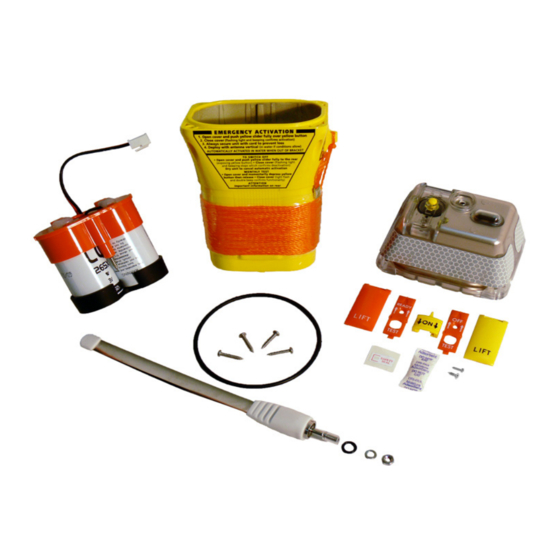
For reasons of economy, the service kit is delivered with both coloured covers and both types of switch slider track. Ensure that you use the one appropriate to your product. 4.2.1 MT400 SERIES BATTERY SERVICE KIT These illustrations show the contents of the battery service kits. - Page 4 4.2.2 MT401 SERIES BATTERY SERVICE KIT Part names are as for the MT400 series battery service kit, see above at Section 4.2.1. 4.2.3 MT403 SERIES BATTERY SERVICE KIT Part names are as for the MT400 series battery service kit, see above at Section 4.2.1.
- Page 5 4.3 REPAIR MATRIX The sequence of operations for each service type is given within Table 4-1. Multiple service types may be combined provided the sequence of operations is maintained. Para. Operation/ Nature of service Routine Battery External inspection Replace- Repair of ment Fault 4.4.1...
- Page 6 4.4.2 EXTERNAL SWITCH MECHANISM This operation is carried out when: • Access to the sealing screw is required. • The switch mechanism or switch cover needs to be replaced. Disassembly For disassembly each step is to be completed in numerical order as follows: 1.
- Page 7 3. Place and tighten the countersunk retention screw to a torque of 50 cN·m ± 5 cN·m. 4. Move the slider switch to the OFF or READY position. WARNING: You must do this within 45 seconds to avoid a live transmission. 5.
- Page 8 2. Using a PH1 Phillips screwdriver, remove all four screws that retain the EPIRB cap to the lower chassis. Discard the screws . 3. Firmly grasp the cap with one hand (not by the antenna), and the lower chassis with the other hand, and fully separate them.
- Page 9 7. Fully discharge the old battery pack and dispose of it in accordance with local regulations. Assembly Assembly consists of essentially the disassembly operations in reverse sequence. Each step is to be completed in numerical order as follows: 1. Ensure that you are using an antistatic mat and wearing the wrist strap. CAUTION: This equipment contains static-sensitive componentry.
- Page 10 6. Fully seat the new O-ring in the groove, ensuring it is fitted evenly with no twists. A blunt instrument may be of assistance. Whichever tool is used ensure that it does not damage the face of the O-ring seal. 7.
- Page 11 4.4.4 CAP DISASSEMBLY / ASSEMBLY This operation is carried out when: • The external antenna and/or seal need to be replaced. • It is necessary to remove the electronic module from the cap. • Access to the internal switch assembly, including the sealing membrane is required. Disassembly For disassembly, each step is to be completed in numerical order as follows: 1.
- Page 12 4. Fit the spring washer and the retention nut to the antenna base. 5. Using a 7 mm hex socket driver, tighten the antenna retention nut to 95 cN·m ± 5 cN·m. 6. Install the PCB. Note the guide slots in the cap; locate the PCB edges into these guide slots before inserting the PCB into the cap.
- Page 13 Sachet Location 5. IMMEDIATELY reseal the EPIRB (4.4.3). 6. Perform a leak test (4.4.6) including insertion of the sealing screw. 4.4.6 LEAK TEST It is vitally important that the integrity of all environmental seals remains intact. Perform this test where: •...
- Page 14 2. Assemble the Dealer Leak Test Kit. Refer to the instructions (part number 310463). 3. Place the EPIRB in the Dealer Leak Test Kit and apply compressed air as described in the instructions (part number 310463). 4. Completely submerse the EPIRB in fresh water and allow any externally trapped air to surface.
- Page 15 If the EPIRB has failed the leak test, it must not be returned to service. It may be necessary to obtain another battery service kit. If it appears that only individual parts are required, check for availability with GME. 4.4.7 SECURITY SEAL REPLACEMENT A failed or torn security seal may lead the owner to question the operational status of the EPIRB.
- Page 16 4.4.8 REPROGRAMMING USER INFORMATION Where the printed circuit board has been replaced, it is necessary to re-enter user preferences and requirements relating to the selected C-S Protocol. A Dealer Programming kit (part number MT400DPK) is required for this operation (refer Table 6-4).
- Page 17 1. Water activated models should be returned to the customer within the sealable plastic bag included as part the MT400 series battery service kit, if being returned out of bracket. Where this bag is not available, obtain another similar sealable bag.
- Page 18 Instructions for replacement of the HRU and bolt are contained within the Float Free Housing Refurbishment Kit. It is generally possible to carry out this service in situ without removing the housing from the structure to which it is mounted. Servicing does not require any particular skills or training and can be completed by the owner within 5 minutes.
- Page 19 EXPLODED VIEW OF CONSTRUCTION MT400/401/403 Note, MT400/401 battery pack shown. Not present on MT403 model types T E C H N I C A L S E R V I C E M A N U A L...
- Page 20 SCHEDULE OF ITEMS FOR SERVICE & REPAIR Product Sales/Order Name / Description Supply Code Quantity 015773 MT401FFsvc Float Free (FF) kit services 1 housing service kit 015772 MT401conc Float Free MT401 kit services 1 conversion kit 019391 MT400svc...
- Page 21 Product Sales/Order Name / Description Supply Code Quantity 013357 61A0355 Mounting bracket common Single base 013358 61A0356 MT400 - mounting bracket Single collar 014617 97MT- MT401 - mounting Single 401MTG bracket collar (complete ...
- Page 22 MT400 external switch service kit Kit services 1 015768 MT401extsw MT401/3 external switch service kit Kit services 1 015767 MT400ant MT400 series antenna service kit Kit services 1 015771 MT400bat MT400 series battery service kit Kit services 1 (complete with lower chassis) 019395...
- Page 23 Air hosing and suitable Single connectors Inline air dryer and Single suitable connectors Beacon tester Single Table 6-5 Tools and Service Equipment gme.net.au GME Pty Ltd 17 Gibbon Road, Winston Hills NSW 2153, Australia Part Number: - Drawing Number: 42772-7...