Advertisement
Quick Links
1
INTRODUCTION
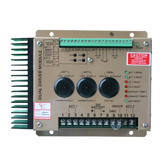
Th e DDM101 is an accessory module whose function is to drive two independent, feed-
back-equipped GAC electronic actuators (see TABLE 1) from one GAC ESD Electronic
Speed Device (see TABLE 2) Th is module is primarily installed where two actuators
are required for a single engine i.e., two independent diesel fuel pumps or two gaseous
throttle body actuators (ATBs).
2
SPECIFICATIONS
DC Input Voltage
Actuator 1 Current
Actuator 2 Current
PWM Drive from Governors
Actuator Position Sensors
ENVIRONMENTAL
Operating Temperature
Humidity
Vibration
Shock
Dual Driver Module
POWER INPUT
18 - 32 VDC(Nominal 24V DC)
Transient protected to +/-250 VDC
Up to 15 Amps, Short Circuit protected
Up to 15 Amps, Short Circuit protected
550 Hz Min from 12-32 V DCMax am-
plitude
5V DC excitation 1 to 4V DC output
40° to +85°C
up to 100%
RELIABILITY
1G, 20-100 Hz
10 G (11ms)
PER CE EN55011, EN50081-2, and
EMC
EN50082-2
DDM101
3
INSTALLATION
In the described applications, the desire is to drive two feedback-equipped, electric
actuators equally so that either banks or cylinder groups receive equal fuel levels. Th e
actuators should be of similar types with similar position sensors with equal outputs. To
equalize the fuel to each cylinder bank the DDM101 has two advanced features, fuel and
exhaust temperature balance. Th e fuel balance feature will correct any unbalances in
the fuel systems by equalizing the fuel being delivered by each actuator. Any diff erences
noted by the accurate actuator position sensors will be nulled out by the electronics so
that the position sensors will track equally throughout the range, unless compensated
with the FUEL BALANCE.
Engine power should be balanced by measuring the exhaust gas temperature readings at
each bank. Some mechanical calibration of the actuator linkage and the fuel rack will be
required to assure that the systems are nearly alike at one fuel delivery point. Th is can
be either idle fuel or any midpoint of load control. Th e FUEL BALANCE adjustment
is then used to set equal engine cylinder power at near 100% of engine load. In order
to achieve minimum diff erence at any load point, the mechanical linkage adjustments
should be set equal at 20% power with the electrical adjustments set equal at 80% power.
Each actuator driver circuit has its own GAIN [ACT 1 and ACT 2] adjustment to
optimize the feedback control loop response. (See TABLE 6)
Refer to (WIRING DIAGRAM 4.) for proper connections. It is suggested that the
DDM101 be mounted along side the Electronic Speed Device (ESD) . When mounting
the unit, attach it to a vertical surface to prevent any moisture from collecting on the
circuit board. Th e normal precautions outlined in the ESD manual should be followed
for the DDM101 as well.
1
DDM101 Duel Driver Module 1.15.19
© 2019 Copyright All Rights Reserved
PIB 4134 F
Advertisement

Related Manuals for Governors America DDM101


Summary of Contents for Governors America DDM101
- Page 1 INSTALLATION INTRODUCTION Th e DDM101 is an accessory module whose function is to drive two independent, feed- In the described applications, the desire is to drive two feedback-equipped, electric back-equipped GAC electronic actuators (see TABLE 1) from one GAC ESD Electronic actuators equally so that either banks or cylinder groups receive equal fuel levels.
- Page 2 PID/ IDLE SPEED ADJUSTMENT/ AUXILLARY ACCESSORY INPUT ESD5111 Standard Unit ESD5131 Switchable Soft Coupling and Lead Circuit ESD5221 Single Element Speed Switch / 10 Amp Relay Output WIRING DIAGRAM DDM101 Duel Driver Module 1.15.19 PIB 4134 F © 2019 Copyright All Rights Reserved...
- Page 3 30° GAIN Governor ˚ on the ESD . Connect Terminal 10 on the DDM101 to Terminal B on the ESD . Connect Terminal 9 of the DDM101 to Terminal E on the ESD . 25 Turn 12 Turns CW Fuel Balance...
- Page 4 Adjusting the DDM101 can also be accomplished by analyzing the ESD’s PWM voltage the TC 1 or TC 2 fault LED will light and the balancing function will shut off . (see input to Terminals 25 and 26 on the DDM101. Th e desirable voltage reading between TABLE 7) Terminals 25 and 26 should measure 7 VDC at no load and 14 VDC at full load.
Need help?
Do you have a question about the DDM101 and is the answer not in the manual?
Questions and answers