Advertisement
Quick Links
1
SPECIFICATIONS
PERFORMANCE
Isochronous Operation
Speed Range / Governor
Speed Drift with Temperature
Idle Speed Adjust Range
Droop Range
Speed Trim Range
Remote Variable Speed
Range
Starting Fuel Adjustment
0.0 - 1.5 A
0.3 - 5.0 A
Overspeed Set Point
Crank Termination Set Point
Terminal Sensitivity
H
M
K
N
INPUT / OUTPUT
Supply
Maximum Continuous Supply
Polarity
Power Consumption
Speed Signal Range
Maximum Actuator Current
Maximum Current, Relay Contact
(Terminals 1 - 6) Rating
Chopping Frequency Range
ENVIRONMENTAL
Ambient Temperature
Relative Humidity
All Surface Finishes
COMPLIANCE / STANDARDS
Agency
Dimension
Weight
Mounting
RELIABILITY
Vibration
Shock
Testing
ESD5300 Series
Speed Control Unit
± 0.25%
1.0 - 7.5 KHz Continuous
± 1% Maximum
25 - 85% of rated speed
0 - 5% for a 1.5 A actuator current change
± 200 Hz
Accel. Adjustment 266 Hz/sec - 1300 Hz/
sec
Decel. Adjustment 250 Hz/sec - 1000 Hz/
sec
120, 175, 225, 275 Actuators / SW2-7 "OFF"
(24 Volt Only) 2001 Actuator / SW2-7 "ON"
2330 Hz - 8500 Hz
200 Hz - 2050 Hz
105 Hz, ±15 Hz/Volt @ 5 K Impedance
130 Hz, ±15 Hz/Volt @ 1 M Impedance
685 Hz, ±40 Hz/Volt @ 326 K Impedance
1000 Hz, ±50 Hz/Volt @ 8 K Impedance
24 VDC Battery Systems
(Transient and Reverse Voltage Protected)
32 Volts
Negative Ground (Case Isolated)
100 mA (no actuator current)
1.0 - 50 VAC
15 A
6 A
60 - 380 Hz
-40° to 85°C (-40 to 185°F)
up to 95%
Fungus Proof and Corrosion Resistant
CE and RoHS Requirements
PHYSICAL
See Section 4 "Outline & Wiring Diagram"
3 lb
Any position, Vertical Preferred
1G, 20-100 Hz
10 G (11ms)
100% Functional Testing
2
INSTALLATION
The ESD5300 speed control unit is rugged enough to be placed in a control
cabinet or engine mounted enclosure with other dedicated control equipment.
The circuit board is conformally coated to seal out moisture and resist vibration.
If water, mist or condensation can come in contact with the controller, it should
be mounted vertically. This will allow any accumulated fl uids to drain away from
the speed control unit.
3 3
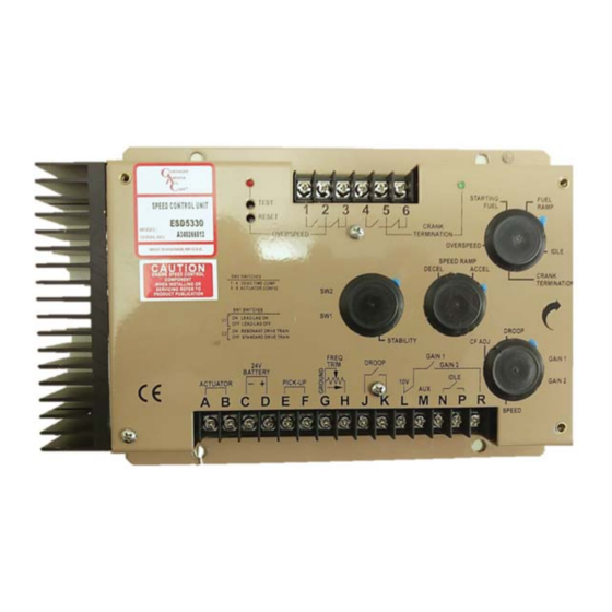
WIRING
WIRING
TERMINAL
DEFINITION
A & B
Actuator (+/-)
Battery Power
C & D
(-/+)
Magnetic
E & F
Pickup
(- is ground)
G
Ground Signal
H
Frequency Trim
TERMINAL
DEFINITION
L & R
Gain 1 & Gain 2 Gain 1 when open / Gain 2 when closed
M
Aux Input
N & P
Idle
RECOMMENDATIONS
1.
Shielded cable should be used for all external connections to the ESD
control.
One end of each shield, including the speed sensor shield, should be
2.
grounded to a single point on the ESD case.
ESD5300 Speed Control Unit 01.04.19
1
NOTES
#14 AWG wire
#14 AWG wire
A 20 amp fuse must be installed in the
positive battery lead to protect against
any overload or short circuit
Battery positive (+) input is Terminal D
Wires must be twisted and/or shielded for
their entire length
Gap between speed sensor and gear
teeth should not be smaller than 0.02 in.
(0.45mm)
Speed sensor voltage should be at least 1.0
VAC RMS during crank
Shielded cable required for lengths over 15
ft (5 m) & connected to Terminal G
NOTES
Load Sharing / Synchronizing, Ground at
Terminal G
Active when closed
© 2019 Copyright All Rights Reserved
PIB 1041 G
Advertisement

Related Manuals for Governors America ESD5300 Series


Summary of Contents for Governors America ESD5300 Series
- Page 1 ESD5300 Series Speed Control Unit SPECIFICATIONS INSTALLATION The ESD5300 speed control unit is rugged enough to be placed in a control PERFORMANCE cabinet or engine mounted enclosure with other dedicated control equipment. The circuit board is conformally coated to seal out moisture and resist vibration.
- Page 2 OUTLINE / WIRING DIAGRAM OUTLINE / WIRING DIAGRAM 10.281 (261,1) 1.250 9.000 (228,6) (31,8) Ø0.281 6.000 (7,1) (152,4) STARTING FUEL OVERNORS TEST FUEL 1 2 3 4 5 6 RAMP MERICA RESET ORP. CRANK SPEED CONTROL UNIT OVERSPEED TERMINATION OVERSPEED ESD5300 IDLE MODEL:...
-
Page 3: Start The Engine
START THE ENGINE IDLE AND RAMP SETTING Close the IDLE switch connecting Terminals N and P. This will cause the engine If the cranking termination occurs too quickly, preventing the engine from start- to slow to an idle speed. Adjust the IDLE setting for desired idle speed. ing, turn the crank termination adjustment CW. -
Page 4: 10 Troubleshooting
TROUBLESHOOTING OVERSPEED MONITOR The overspeed monitor circuit trip point is set by the multi-turn potentiometer. This is normally set by raising the engine speed to the specifi c trip point speed SYSTEM INOPERATIVE and turning the adjustment CCW until the O.S. circuit turns ON (Red LED). This If the engine governing system does not function, the fault may be determined will also turn off the actuator output circuit and change the state of the internal by performing the voltage tests described in Steps 1 through 3. - Page 5 SW2 SWITCH SETTINGS FOR INSTABILITY INSUFFICIENT MAGNETIC SPEED SIGNAL SLOW INSTABILITY FAST INSTABILITY SW2-1 SW2-2 SW2-3 SW2-4 The speed control unit will govern well with 1.0 VAC RMS speed sensor signal. SEQUENCE SEQUENCE A speed sensor signal of 3 volts RMS or greater at governed speed is recom- mended.
Need help?
Do you have a question about the ESD5300 Series and is the answer not in the manual?
Questions and answers