Table of Contents
Advertisement
Quick Links
PONOVO POWER CO., LTD
No. 139 Jinghai Third Road, BDA, Beijing, China, 100176
Office
Tel. +86 (10) 59089666
E-mail
info@relaytest.com
Website
www.relaytest.com / www.ponovo.com.cn
VERSION:
DATE:
This manual is the publisher of PONOVO POWER CO., LTD. To make any kind of copy of
this manual please contact PONOVO POWER CO., LTD in advance.
PNS630 User Manual
PNS630-AE-1.20
JULY, 2020
PNS630 Handheld Analyzer User Manual
Advertisement
Table of Contents

Summary of Contents for Ponovo PNS630
- Page 1 Website www.relaytest.com / www.ponovo.com.cn PNS630 User Manual VERSION: PNS630-AE-1.20 DATE: JULY, 2020 This manual is the publisher of PONOVO POWER CO., LTD. To make any kind of copy of this manual please contact PONOVO POWER CO., LTD in advance.
-
Page 2: Table Of Contents
PNS630 Handheld Analyzer User Manual Content 1. General ......................1 1.1 Introduction ..................1 1.2 Features ....................2 2. Technical Specifications ................3 2.1 Specifications..................3 2.1.1 Dimension and Weight ............... 3 2.1.2 Interfaces ..................3 2.1.3 Power Supply ................4 2.1.4 Environment ................ - Page 3 PNS630 Handheld Analyzer User Manual 6.1.2 BI Mapping ................34 6.1.3 Basic Setting ................35 6.1.4 Parameter ................. 35 6.1.5 Result ..................36 7. Sequence ....................37 7.1 Main Interface ..................37 7.2 Sequence Edit ................... 38 7.2.1 SMV ..................38 7.2.2 GOOSE ..................
- Page 4 PNS630 Handheld Analyzer User Manual 9.4 Statistics .................... 63 9.5 Message Monitor ................65 9.6 GOOSE Publish ................. 66 9.7 GOOSE Send State ................67 9.8 GOOSE Bit Monitor ................68 10. Time ......................69 11. Network Flow ................... 71 12.
- Page 5 PNS630 Handheld Analyzer User Manual Notes: Disconnect the external circuit of the relay to assure precision. Do not block the ventilation outlets. Avoid the equipment being wet by rain. Do not switch-on and operate the equipment in the place having explosive gas or water vapor.
-
Page 6: General
Message sending (IEC61850-9-2, IEC60044-8, GOOSE message) and GOOSE subscribe function can meet the requirement of digital relay test. B code, IEC61588 and optical power measurement are supported. Portable, stable, humanized PNS630 is the effective device for smart substation maintenance. -
Page 7: Features
PNS630 Handheld Analyzer User Manual 1.2 Features 1) Support IEC 61850-9-2, IEC 61850-9-2 (2.0), IEC 60044-7/8, GOOSE, IRIG-B and IEEE1588 standards. 2) Support SCD, ICD, CID files analysis to get sampling value, sampling channel and GOOSE signal configuration. 3) Support SMV ang GOOSE monitor, and record the abnormal messages. -
Page 8: Technical Specifications
PNS630 Handheld Analyzer User Manual 2. Technical Specifications 2.1 Specifications 2.1.1 Dimension and Weight ⚫ Dimension: 190mm (W)× 210mm (H)× 64 mm (D) ⚫ Weight ≤1.35 kg 2.1.2 Interfaces Interface Function 1 port to receive IRIG-B code. 1 port to send IRIG-B code. -
Page 9: Power Supply
PNS630 Handheld Analyzer User Manual 2.1.3 Power Supply ⚫ Battery: 12.6V 4400mAh lithium battery ⚫ Power adaptor: Input: AC 100~240V, 50/60Hz Output: DC 15V, 1.66A ⚫ Battery charge: 4~6 hours charging time per once The charging time is suggested more than 12 hours in the first three times. -
Page 10: Performance
PNS630 Handheld Analyzer User Manual 2.2 Performance 1) Dynamic response time < 2s 2) Remote measurement response < 2s 3) Remote information response time < 2s 4) Transimission distance > 1km,output accuracy 0.5 class 5) The average largest error of sending SMV < 1us. -
Page 11: Panel Description
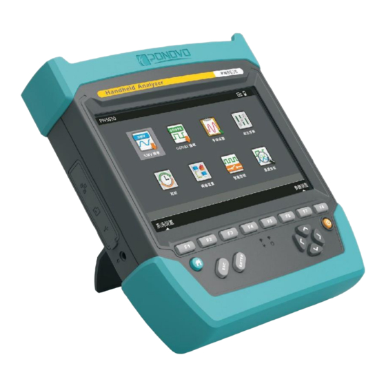
PNS630 Handheld Analyzer User Manual 3. Panel description 3.1 Front Panel This is the PNS630 front panel. The keys and its functions are as below information. PNS630 Front panel 1. Color touch-screen 7 inches. 2. Function keys: Each key has its own functions that are indicated in each module. -
Page 12: Top Panel
PNS630 Handheld Analyzer User Manual 3.2 Top Panel PNS630 Top panel 1. Optical Ethernet port 1-4: LC Rx port to send and receive IEC61850-9-2, GOOSE and IEEE1588. 2. Optical serial port TX1: Reserved port. Optical serial port TX2: ST port to send IRIG-B code. -
Page 13: Left Panel
PNS630 Handheld Analyzer User Manual 3.3 Left Panel 1. Ethernet port RJ45: Receive and send MMS messages by Ethernent. 2. SD card: Used to import the configuration file, save record files, and screenshot pictures. 3. USD device: Connect with computer. -
Page 14: Operations
PNS630 Handheld Analyzer User Manual 4. Operations 4.1 Power on/ Power off Press switch button to power on or power off. 4.2 Main Interface There are 14 modules: SMV, GOOSE, Quick Test, Sequence, Time, Net Flow, IED, Waveform, Optical Power, Network and MU Delay, MMS, SOE, CheckPhasor. - Page 15 PNS630 Handheld Analyzer User Manual Main interface SMV: Receive SMV messages and display the analysis results in rms, waveform, sequence, phase, power, phase-check, polarity, harmonic and real-time messages and make a record on the drop-frame messages. GOOSE: Receive GOOSE messages and show the real-time value, bit-change, message record, monitor and test GOOSE sending mechanism.
- Page 16 PNS630 Handheld Analyzer User Manual Main interface Optical power: Show the real value, average value, max value and min value received by each port. Network: Control the present flow by sending SMV, GOOSE and network in each port. MU delay: Receive time signal, test MU channel time delay, synchronization accuracy and timekeeping accuracy.
-
Page 17: Parameter
In the setting page, choose “Settings” showing below to start settings. PNS630 Device settings Backlight time: Set the backlight time, PNS630 will be staying saver state without no operation during the setting time. Home function: two choices are available, home and PrintScreen Home: Press Home to get back to the main interface. -
Page 18: Parameter
PNS630 Handheld Analyzer User Manual 5.2 Parameter In parameter, there is the configuration file, frequency, voltage, current channel and primary/secondary value, time synchronization plan and message send method as below. Parameter SCL Import: Select the SCL configuration file used in present station and touch Import or... - Page 19 PNS630 Handheld Analyzer User Manual Note: The SCL files should be saved in the SD card in advance. Rated frequency Fnom, Vnom and Inom: the rated frequency, voltage and current based to analyze the messages. PT1-PT4: the default primary/ secondary voltage in four channels.
-
Page 20: Smv Output
PNS630 Handheld Analyzer User Manual 5.3 SMV Output SMV output is valid only in Quick Test and Sequence modules. The ASDU and sample rate can be edited. There are 16 channels of voltage, 16 virtual current channels, in 4 groups. - Page 21 PNS630 Handheld Analyzer User Manual SMV output SMV Std: the supported SMV standards include IEC61850-9-2, 61850-9-2 (2.0), and 60044-7/8 (reserved). Sampling rate: Set the samples per nominal period. ASDU: Application service data unit. Add SMV: Touch “Add SMV” or press F2 to open the menu.
- Page 22 PNS630 Handheld Analyzer User Manual Add SMV Import from SCL: Import from the station configuration SCL files. Press Import from SCL and press Enter to the import page. The available SCL files are listed below. The same APPID in the SCL file will not be added twice.
- Page 23 PNS630 Handheld Analyzer User Manual The below picture is the control block list after adding SMV. Contorl block after adding SMV Delete: Press Del to delete the present SMV output. Port: Choose the required port. Clear: Touch Clear on screen or press F3 to delete all the blocks listed.
- Page 24 SMV output, the required control block can be chosen or cancelled. In Quick Test and Sequence test, only the chosen blocks will be sent as set. Maximum 4 groups of SMV blocks can be sent at the same time by PNS630. The SMV blocks chosen...
-
Page 25: Goose Publish
Max repeitition interval(T0) (ms): The default time is 5,000. Fast repetitions (T1) (ms): Set GOOSE time interval T1 and default value 2. PNS630 will make GOOSE publish as below diagram. When there is bit-change during GOOSE data transmission, it will re-send GOOSE messages in total 5 frames. When the bit-change begins, it starts sendng the 1 frame. - Page 26 PNS630 Handheld Analyzer User Manual GOOSE Publish process Add GOOSE: Touch “Add GSE” or press F2 to open the menu. Import from SCL and manual add, there are two methods available. The way of Add GOOSE publish is the same as that of add SMV.
- Page 27 PNS630 Handheld Analyzer User Manual Add GOOSE 1) Import from SCL: Press Import from SCL and press Enter to the import page. The available SCL files are listed below. The same APPID in the SCL file will not be added twice.
- Page 28 PNS630 Handheld Analyzer User Manual The below picture is the control block list after adding GOOSE. The control block after manual add GOOSE Del: Press Del to delete the present block. Port: Choose the required port. Clear: Touch Clear on screen or press F3 to delete all the blocks listed.
- Page 29 In the GOOSE publish, the required control block can be chosen or cancelled. In Quick Test, Sequence test and IED, only the chosen blocks will be sent as set. Maximum 6 groups of GOOSE blocks can be sent at the same time by PNS630.
- Page 30 PNS630 Handheld Analyzer User Manual Choose GOOSE publish blocks...
-
Page 31: Goose Subscribe
PNS630 Handheld Analyzer User Manual 5.5 GOOSE Subscribe GOOSE subcribe is valid in Quick Test, Sequence and IED modules. GOOSE subscribe has no effect on the GOOSE message monitor. The GOOSE subscribe setting process is as below. Add GOOSE block-> Choose GOOSE block-> Choose GOOSE channel-> Check BI mapping Add GOOSE subscribe: Touch “Add GSE”... - Page 32 PNS630 Handheld Analyzer User Manual Import from SCL file Manual Add: If there is no control block, a default control block will be added. If there is an existing control block, the configuration of this control block will be copied to the added GOOSE control block.and the APPID will be adding 1.
- Page 33 PNS630 Handheld Analyzer User Manual In control block page, touch Channel or press F3 to enter into the channel edit page. The channel name, map and quality information can be set. In Quick Test, Sequence test and IED, the GOOSE subscribe is activated.
-
Page 34: Binary
PNS630 Handheld Analyzer User Manual 5.6 Binary In Binary, the statbled time of binary output and binary input type can be set here. Stablized time: Generally, 10ns is set. BI type: Potential-free or Potential-Sensing. Binary... -
Page 35: About
PNS630 Handheld Analyzer User Manual 5.7 About Select About to get the kit information. About... -
Page 36: Quick Test
PNS630 Handheld Analyzer User Manual 6. Quick Test In Quick Test, the messages will be sent as default value set here. Screen touches the Quick Test module to enter into the test interface. Quick Test Interface Press F2 to switch between SMV and GOOSE. - Page 37 +: Increace as step; -: Decreace as step Lock/ Unlock: In lock mode, the PNS630 will maintain the SMV sent previously. The value can be changed, but the output items. In unlock mode, the changed setting value will be mapped to the channel of the SMV control block and send SMV messages and receive the binary mapped by the GOOSE subscribe.
-
Page 38: Exsetting
PNS630 Handheld Analyzer User Manual All off: Set the bit change type of data as off. All reverse: Set all the channel data reverse. Test/Reset: Test or reset the GOOSE channel. 6.1 ExSetting There are SMV Mapping, BI Mapping, Basic setting, Parameter and TestResult setting options in Quick Test. -
Page 39: Smv Mapping
PNS630 Handheld Analyzer User Manual 6.1.1 SMV Mapping It shows the mapping relationship between SMV sampling channel and the built-in voltage/ current virtual channel. Please refer to the mapping setting in Chapter 5.3 SMV output. SMV mapping 6.1.2 BI Mapping It shows the mapping relationship between GOOSE subscribe channel and the built-in DI channel. -
Page 40: Basic Setting
PNS630 Handheld Analyzer User Manual 6.1.3 Basic Setting Basic setting Remain the time: In Lock mode, the output time can be hold after receving the binary trigger signal. Time mode: Mapping or bit-change DC setting: three channels of output current and four channels of output voltage each can be chosen here. -
Page 41: Result
PNS630 Handheld Analyzer User Manual 6.1.5 Result It includes the SMV output, GOOSE changed item and BI change results. Result Changed time: the time between SMV/ GOOSE value change and test start time. Changed item: Show the SMV or GOOSE change BI change: GOOSE binary bit change caused by the SMV or GOOSE subscribe changes. -
Page 42: Sequence
PNS630 Handheld Analyzer User Manual 7. Sequence In Sequence, one group status can be prefault set and SMV output. The testing will be started as prefault settings with maximum 10 statuses. Different switch methods are available, for example, IRIG-B code or manual. -
Page 43: Sequence Edit
PNS630 Handheld Analyzer User Manual 7.2 Sequence Edit Choose the sequence item to be edited and press Edit to enter into below page. 7.2.1 SMV It shows the channel, amplitude, angle and freqeuence. The setting is the same as in Quick Test. -
Page 44: Parameter
PNS630 Handheld Analyzer User Manual 7.2.3 Parameter Set trigger condition, hold time and trigger value. Parameter (1) Trigger Condtion Time trigger, B code trigger, manual trigger, and binary trigger. a.) Time Trigger: Trigger as duration time Output time(ms): set time for the state duration... - Page 45 PNS630 Handheld Analyzer User Manual b.) B code Trigger: Trigger by set time from GPS - IRIG-B Time (hh: mm: ss): set the state trigger time Hardware time: show the current time B code Trigger c.) Manual Trigger: Trigger by key F3...
- Page 46 PNS630 Handheld Analyzer User Manual d.) Binary Trigger: Trigger by Binary input (GOOSE) BinaryLogic: Or or And. Thold: the hold time after trigger Binary Trigger (2) Binary Trigger as per the set binary. One or multiple binary channels can be set.
-
Page 47: States
PNS630 Handheld Analyzer User Manual 7.2.4 States Quick switch into other states. 7.2.5 SV Group Quick switch into other SV Groups. -
Page 48: Calculate
PNS630 Handheld Analyzer User Manual 7.2.6 Calculate The state can be corrected according to the result calculated. Calculate Fault type: A-E, B-E, C-E, A-B, B-C, C-A, A-B-E, B-C-E, C-A-E, A-B-C Z/P: Z, phi and R, X Constant type: I const, V const and Zs const. -
Page 49: Smv
The remote measurement data can be shown in table, waveform, vector diagram, sequence, Power, Harmonic, Polarity, Statistics, Message monitor and compare dual AD input. Before SMV, the PNS630 should be connected in the net. -
Page 50: Smv Detect
PNS630 Handheld Analyzer User Manual 8.1 SMV Detect In SMV detect, all the control block information in the net will be displayed here. Choose the control blocks required to phase check or analyzer the messages. Note: 9-2: IEC 61850-9-2, IEC 61850-9-2(2.0); FT3(RSRV): 60044-7/8 (Reserved FT3) 8.2 Effective Value... - Page 51 PNS630 Handheld Analyzer User Manual If there are more than two control blocks are chosen, press Control block to swtich between different blocks. SMV function Press Exmenu to set other items. SMV Exmenu...
- Page 52 PNS630 Handheld Analyzer User Manual Select the Monitor to check all the control blocks’ information and syn status. SMV Monitor SMV status monitoring is to check the status of SV. The contents of the checking include Validity, Maintenance required, Harmonics/Inter-harmonics and Quality.
- Page 53 PNS630 Handheld Analyzer User Manual Choose Display Primary or Display Secondary to check the primary/ secondary value. SMV Channel setting In SMV channel setting, the SMV channel type, phase can be modified. Type: different channel type such as different voltage and current, has different conversion ratio, further gets different testing value.
-
Page 54: Waveform
PNS630 Handheld Analyzer User Manual 8.3 Waveform In SMV RMS interface, choose Waveform in Function menu. SMV Waveform Switch the SMV channel by screen touch and press keys to down or up. The waveform can be adjusted according to the function keys. -
Page 55: Vector
PNS630 Handheld Analyzer User Manual 8.4 Vector In SMV RMS interface, choose Vector in Function menu. The vector diagram with 4 current/ voltage of present SMV can be displayed as below. SMV Vector... -
Page 56: Sequence Component
PNS630 Handheld Analyzer User Manual 8.5 Sequence Component In SMV RMS interface, choose Sequence component in Function menu. 3 phase of voltage or current’s sequence component diagram of present SMV control block can be shown here. Current sequence component Current sequence component... -
Page 57: Power
PNS630 Handheld Analyzer User Manual 8.6 Power In SMV RMS interface, choose Power in Function menu. The voltage of phase A, B, C, active power, reactive power, power factor, apparent power information will be shown here. SMV Power interface The voltage and current can be set, and the power in single phase or 2-phase can be... -
Page 58: Harmonic
PNS630 Handheld Analyzer User Manual 8.7 Harmonic In SMV RMS interface, choose Harmonic in Function menu to show the DC, fundamental and harmonic information of the selected SMV control block. SMV Harmonic interface (Table) SMV Harmonic interface (Bar chart) Press valid value to switch into harmonic interface in bar chart. Maximum 21 times of harmonics can be analyzed. -
Page 59: Dual Ad
PNS630 Handheld Analyzer User Manual 8.8 Dual AD In SMV RMS interface, choose Dual AD in Function menu to show the dual AD information such as value of AD1-AD2, ⃒AD1-AD2⃒ and phase difference. SMV Dual AD interface... -
Page 60: Polarity
PNS630 Handheld Analyzer User Manual 8.9 Polarity In SMV RMS interface, choose Polarity in Function menu. The polarity is mainly used for digital voltage/ current transformer in testing polarity. Check the pointer swing. If it swings to “-”, it indicates the transformer with negative polarity;... -
Page 61: Statistics
PNS630 Handheld Analyzer User Manual 8.10 Statistics In SMV RMS interface, choose statistics in Function menu to display the frame-drop information. SMV Statistics interface Press Clear to reset all the information to 0 and start the statistics. Message total frame number: The total received message since start... - Page 62 PNS630 Handheld Analyzer User Manual Dispersion: Show the message dispersion in chart bar. The time difference among all the messges received during the setting time. 0 means no difference, 1 means difference within 1us, 250 means difference within 250us or exceeding 250us.
-
Page 63: Message Monitor
PNS630 Handheld Analyzer User Manual 8.11 Message Monitor In SMV RMS interface, choose monitor in Function menu to check the messages in real-time and compare it with SCD file. If there is difference, it will light in red. SMV monitor... -
Page 64: Goose
PNS630 Handheld Analyzer User Manual 9. GOOSE In GOOSE, it receives and analyzes GOOSE message with GOOSE channel, data type and frame information. The PNS630 should be connected with the IED or switchgear before making GOOSE test. GOOSE detect interface... -
Page 65: Goose Detect
PNS630 Handheld Analyzer User Manual 9.1 GOOSE Detect In GOOSE detect, all the control blocks in the networks will be listed here. The GOOSE detect time depends on the T0 of the control blocks. GOOSE detecting... -
Page 66: Real Value
PNS630 Handheld Analyzer User Manual 9.2 Real Value In GOOSE detect, press Enter to enter into the real value page to check the GOOSE information including channel, data type and value. All the information here is showing in real-time at cycle 1s. -
Page 67: Bit-Change List
PNS630 Handheld Analyzer User Manual 9.3 Bit-Change List In function list, choose Bit-change list to check the bit change information. No.: The number of bit-change. ChangedTime: The time of bit-change Channel: The channels with bit-change GOOSE Bit-change Press enter to check the bit-change for each item. -
Page 68: Statistics
PNS630 Handheld Analyzer User Manual 9.4 Statistics In Statistic, the abnormal GOOSE message can be tracked. GOOSE Statistics Press Refresh to reset the statistics to zero and re-start record. Message total fram number: The total message from beginning. SqNum Loss: Record the frame-drop number. The SqNum will keep increasing when StNum does not change. - Page 69 PNS630 Handheld Analyzer User Manual GOOSE Statistics Virtual deformation: When the received StNum keeps increasing, it is bit-change happened. But when the channel does not change in GOOSE, it is virtual deformation. Testing mode: When it is 1, it is the testing mode.
-
Page 70: Message Monitor
PNS630 Handheld Analyzer User Manual 9.5 Message Monitor In message monitor, the message information can be checked in real-time and compared between the received GOOSE message and SCD file. If there is difference, it will be marked in red. GOOSE message monitor... -
Page 71: Goose Publish
PNS630 Handheld Analyzer User Manual 9.6 GOOSE Publish In GOOSE publish method, the received GOOSE method can be checked, including Absolute time, interval time, StNum and SqNum. GOOSE method... -
Page 72: Goose Send State
PNS630 Handheld Analyzer User Manual 9.7 GOOSE Send State In GOOSESendState, the received GOOSE can be checked, including T0,T1,T2,T3 and StNum,SqNum. GOOSE Send State... -
Page 73: Goose Bit Monitor
PNS630 Handheld Analyzer User Manual 9.8 GOOSE Bit Monitor In GOOSEBitMonitor, the received GOOSE can be monitor, show true or false. GOOSE Bit Monitor... -
Page 74: Time
If there is no time source, it will show unsynchronized. IRIG-B code In IRIG-B code, it shows the B-code time and synchronization. IEEE1588 shows the time source. Time: First fill in the TimeSetting, press the “Time”, the PNS630, as a time source, could sent the time to other devices. - Page 75 PNS630 Handheld Analyzer User Manual IEEE 1588 Time-Sent...
-
Page 76: Network Flow
PNS630 Handheld Analyzer User Manual 11. Network Flow When there is heavy message flow in IED, we will use the network flow to check. Network flow Package Type: SMV, GOOSE and IEEE1588 Message Number: Number Flow KB/s: the flow rate Percent: the rate between one message type and the total messages. -
Page 77: Ied
PNS630 Handheld Analyzer User Manual 12. IED The main function of IED module is to test the delay time between the GOOSE and Binary of the IEDs (Intelligent Electronic Device) There are two test items in this module: (1) GOOSE → Binary Input (GSE→BI) The time delay from GOOSE to binary input. -
Page 78: Waveform Record
PNS630 Handheld Analyzer User Manual 13. Waveform Record In waveform, it records the waveform and exports the messages to analyze, statistic and playback for further analysis. SMV: Detect SMV messages and select SMV messages. SMV record GOOSE: Detect GOOSE and select GOOSE messages. - Page 79 PNS630 Handheld Analyzer User Manual All: all SMV and GOOSE is selected and recorded. Record/StopRecord: Start or stop record. When stop record it will topup to type name then save the recorded as pcap file. Detect: detect SMV and GOOSE.
- Page 80 PNS630 Handheld Analyzer User Manual Select SMV or GOOSE SMV package list Touch analysis package or press F8 into Analysis package...
- Page 81 PNS630 Handheld Analyzer User Manual SMV Statistics SMV Waveform analysis...
- Page 82 PNS630 Handheld Analyzer User Manual GOOSE GOOSE packagelist...
- Page 83 PNS630 Handheld Analyzer User Manual GOOSE Statistics GOOSE Analysis Difference: check the different bettew current frame and pre frame.
-
Page 84: Optic Power
PNS630 Handheld Analyzer User Manual 14. Optic Power In optic power, it checks the optic power in real-time and records the minimum and maximum value to calculate the average optic power. Optic power Port: optic Ethernet port and optic serial port Real value (dBm): The optic power in real-time Average value (dBm): it is by calculation. -
Page 85: Network
PNS630 Handheld Analyzer User Manual 15. Network In network, it tests the message type, number and messageflow. Message type: SMV, GOOSE, IEEE1588 and others. Message flow rate: the total flow of message and optic port. Output port: the fiber optic port1... -
Page 86: Mu Delay
In MU delay, it tests the time delay between MU data conversion, or the accuracy of MU Clock synchronization test (Time synchronization test and punctuality test). 16.1 MU Delay Test The same clock sends signal to both PNS630 and IED to check the received time delay between PNS630 and MU. Test wiring... - Page 87 For example, to test this delay item of the PSMU 602GC-E MU unit. Its rated channel delay is 1308us, and the test result of channel message response time by the PNS630 is 1311us. In general, the sampling synchronization error should be no more than ±1...
-
Page 88: Sync. Test
PNS630 Handheld Analyzer User Manual 16.2 Sync. Test The time difference between PNS630 receiving PPS signal and IRIG-B code signal. Test wiring 1 Test wiring 2... - Page 89 MU Sync. Test GPS clock source status: Validity or Invalidity. Valid: It means that the RX1 channel of PNS630 has received the B code timing signal from an external standard GPS clock source. Invalidity: If no B code timing signal is received, the display is invalid.
- Page 90 PNS630 Handheld Analyzer User Manual For example, to test the PSMU 602GC-E MU unit. Its PPS type is valid falling edge. Have the GPS source (Test wiring 1) No GPS source (Test wiring 2)
-
Page 91: Time Test
PNS630 Handheld Analyzer User Manual 16.3 Time Test When the MU’s synchronization signal is lost, PNS630 will compare the time error of reveiving PPS signal from IED and the GPS signal received in 10 minutes. Test wiring... - Page 92 MU Timekeeping Test GPS clock source status: Validity or Invalidity. Valid: It means that the RX1 channel of PNS630 has received the B code timing signal from an external standard GPS clock source. Invalidity: If no B code timing signal is received, the display is invalid.
- Page 93 PNS630 Handheld Analyzer User Manual For example, to test the PSMU 602GC-E MU unit. Its PPS type is valid falling edge. PPS type: Falling edge (-) PPS type: Rising edge (+) In general, the sampling synchronization error should be no more than ±1 microsecond.
-
Page 94: Mms
17. MMS In the MMS (Manufacturing Message Specification) module, the IEC61850 communication model of the IEDs is read by the PNS630, which contains information such as communication data, data sets and report control blocks. We introduce the interfaces of the MMS module by connecting the PCS978 digital transformer protection device of NARI. - Page 95 PNS630 Handheld Analyzer User Manual The IP address of the PNS630 needs to be set. The request is on the same network segment as the IP address of the IEDs. In this example, it is on the same network segment as 192.168.1.78.
- Page 96 PNS630 Handheld Analyzer User Manual Return to the previous interface and click "Connect". PNS630 starts to getting models.
- Page 97 PNS630 Handheld Analyzer User Manual Create the report. Get the model successfully.
- Page 98 PNS630 Handheld Analyzer User Manual RPT view: Report view, Real-time data view. Setting: System and protection settings Platen: Platen information, paths, description, and values, etc. TLI info: Trip Logic IEDs/Devics information, Protection trip event. Telemetry info: Telemetry information, paths, description, and values, etc.
-
Page 99: Rpt View
PNS630 Handheld Analyzer User Manual 17.1 RPT View Pause/ Continue: Control the reading of real-time data. Clear: Clear current data. Call: General call. RPTSetting: Report Setting. Cache, non-cache, report trigger optinal, etc. -
Page 100: Rpt Setting
PNS630 Handheld Analyzer User Manual 17.2 RPT Setting (1) Control block select: Cache report block or Non-cached report block. (2) Report trigger optional: Data change, Quality change, Data Update, Cycle delivery, General interrogation. (3) Control block name and statue (activate/ inactivate). - Page 101 PNS630 Handheld Analyzer User Manual Close the report successfully Open the report successfully Refresh report successfully...
-
Page 102: Setting
PNS630 Handheld Analyzer User Manual 17.3 Setting Protection: the settings of digital protection device. System: the settings of substation system. Read: Read the setting from IEDs. -
Page 103: Platen
PNS630 Handheld Analyzer User Manual 17.4 Platen dsRelay Ena:... -
Page 104: Tld Info
PNS630 Handheld Analyzer User Manual 17.5 TLD Info Protection device predefined Dataset: dsTripInfo: Protection event dsRelayDin: Relay protection teleindication dsRelayEna: Relay protection platen dsRelayRec: Protection recording dsRelayAin: Protection telemetry dsAlarm: Protection signal dsWarning: Alarm signal dsCommState: Communication condition dsParameter: Device parameter... - Page 105 PNS630 Handheld Analyzer User Manual Read: Succeed in reading data settings: same as the report settings.
-
Page 106: Telemetry Info
PNS630 Handheld Analyzer User Manual 17.6 Telemetry Info Read: reading data settings: same as the report settings. -
Page 107: Soe
PNS630 Handheld Analyzer User Manual 18. SOE For SOE time test to simulate multiple bit-change events. This function can set the interval time and the times of the GOOSE to Bin.In or Bin.Out to GOOSE, then test the conversion delay time of these test points, and finally obtain the average of the delay time according to the test results. - Page 108 PNS630 Handheld Analyzer User Manual SOE result Total NO.: Total number of bit-change event. Ave. Time (ms): The average delay time for all the bit-changes Total times: Ordinal number Goose bit time/ Bin.bit time: Test point time based on interval time Bin.bit time/ Goose bit time: Return time of each test point...
-
Page 109: Phase-Check
PNS630 Handheld Analyzer User Manual 19. Phase-check In SMV RMS interface, choose Ph-check in Function menu. SMV Ph-check interface (Graph) - Page 110 PNS630 Handheld Analyzer User Manual SMV Ph-check interface (Sheet) PNS630 supports the MU data with 2 phase-checks. Choose one channel of voltage as referece, and its amplitude, phase, frequency, amplitude difference, and angle difference as reference as well to check the next voltage phase-sequence and RMS in the same side or different side.
-
Page 111: Standard Accessories
PNS630 Handheld Analyzer User Manual 20. Standard Accessories Notes: The pictures are for reference only. 1. Package bag Amount: 1 piece The PNS630 Wiring Accessory Package contains the following articles: 2. Optical Cable LC-ST Optical cable LC-LC Optical cable ST-ST Optical cable... - Page 112 It connects the PNS630 with power supply socket. 4. Power Plug Adapter Amount: 1 piece It’s supplied the relevant plug socket according to different countries 5. PC Control Cable (LAN) Amount: 1 piece The LAN cable connects the PNS630 with PC for communications.
- Page 113 PNS630 Handheld Analyzer User Manual 6. Micro SD card Amount: 1 piece It’s used to store the program and testing data. It’s usually inserted inside of the PNS630. 7. Micro SD Card Reader Amount: 1 piece It reads and writes the data from the Micro SD card.
-
Page 114: Appendix 1: Example For Ied And Soe
PNS630 Handheld Analyzer User Manual Appendix 1: Example for IED and SOE In this example, we used PNS630 to test the delay time of GOOSE → Binary Input, Binary Output, and SOE for IED-PSIU621GC (From SAC, Guodian Nanjing Automation Co., Ltd.). - Page 115 PNS630 Handheld Analyzer User Manual ① : +220V ② : -220V / Common port ③ : DI _Binary input closed ④⑤ : DO _Relay Trip, Binary output ⑥ : CUP_Fiber port 2-0 ①: PNS630_ LC Rx port to send and receive IEC61850-9-2, GOOSE and IEEE1588 ②: Binary input (BI), Receive binary input signal...
- Page 116 PNS630 Handheld Analyzer User Manual (2) PNS630_Set the Parameter a.) Import the SCL file_PONOVO LAB b.) Parameter...
- Page 117 PNS630 Handheld Analyzer User Manual c.) Add Goose Publish Message...
- Page 118 PNS630 Handheld Analyzer User Manual d.) Mapping with the IEDs Binary output ports...
- Page 119 PNS630 Handheld Analyzer User Manual e.) Add Goose Subscribe Message...
- Page 120 PNS630 Handheld Analyzer User Manual f.) Mapping with the IEDs Binary input ports...
- Page 121 PNS630 Handheld Analyzer User Manual g.) Binary (3) IED Tests and Results Enter to IED module...
- Page 122 PNS630 Handheld Analyzer User Manual a.) Test the trip time of GOOSE → Binary Input ① F3: (GES→BI); ② F2: Send, send the GOOSE message to IEDs; ③ Touch the screen: switch False/ Ture, send the bit-change message Get the trip time.
- Page 123 PNS630 Handheld Analyzer User Manual b.) Test the delay time of Binary Output → GOOSE ① F4: (BO→GES); ② F2: Send, send the Binary output to IEDs; ③ Touch the screen click the or press the button F6: change the binary state between...
- Page 124 PNS630 Handheld Analyzer User Manual ④ Get the time. (4) SOE Tests and Results Enter to SOE module...
- Page 125 PNS630 Handheld Analyzer User Manual GOOSE to Bin.in Mode Press the button F3 (Para.), set those parameters. Press the button F4(Result), go to the Result interface. Press the button F2(Send), send those messages, when the test is finished, you will...
- Page 126 PNS630 Handheld Analyzer User Manual Bin.out to GOOSE Mode Press the button F3(Para.), set those parameters. Press the button F4(Result). Press the button F2(Send), when the test is finished, get the test results.
Need help?
Do you have a question about the PNS630 and is the answer not in the manual?
Questions and answers