Puls DIMENSION CD Series Manual
Dc/dc converter 24v/24v, 10a, 240w
Hide thumbs
Also See for DIMENSION CD Series:
- Manual (27 pages) ,
- Instruction manual (4 pages) ,
- Manual (22 pages)
Table of Contents
Advertisement
Quick Links
CD-Series
G
D
ENERAL
ESCRIPTION
The CD10.241 is a DIN-rail mountable DC/DC converter
of the DIMENSION series which provides a floating,
stabilized and galvanically separated SELV/PELV output
voltage.
The CD-Series is part of the DIMENSION power supply
family. The most outstanding features of CD10.241 are
the high efficiency, the small size and the wide
operational temperature range.
The CD-Series includes all the essential basic functions.
The devices have a power reserve of 20% included,
which may even be used continuously at temperatures
up to +45°C.
High immunity to transients and power surges as well as
low electromagnetic emission and a large international
approval package for a variety of applications makes
this unit suitable for nearly every situation.
O
N
RDER
UMBERS
DC/DC Converter
CD10.241
Accessory
ZM2.WALL
ZM12.SIDE
YR20.246
Jul. 2017 / Rev. 1.1 DS-CD10.241-EN
after a 5 minutes run-in time unless otherwise noted.
Wall mount bracket
Side mount bracket
Redundancy module
All parameters are typical values at 24V, 10A, 24Vdc input voltage, 25°C ambient and
www.pulspower.com Phone +49 89 9278 0
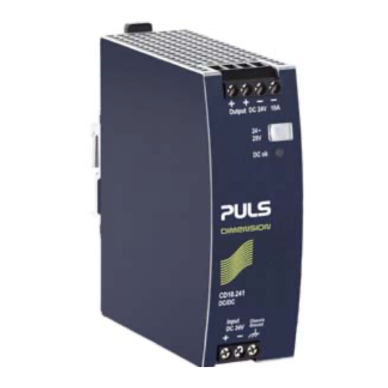
DC/DC Converter 24V/24V, 10A, 240W
DC/DC C
ONVERTER
24V DC-Input
Isolated 24Vdc Output
Efficiency 94.2%
Width only 42mm
20% Output Power Reserves
Full Power Between -25°C and +60°C
Soft-start Function
Minimal Inrush Current Surge
Reverse Input Polarity Protection
3 Year Warranty
S
-
D
HORT
FORM
Output voltage
DC 24V
Adjustment range
24 - 28V*)
Output current
12 – 10.3A
10 – 8.6A
7.5 – 6.5A
Derate linearly between +45°C and +70°C
Input voltage
DC 24V
Input voltage range 18 to 35Vdc
Input current
typ. 10.5A
Input inrush current typ. 6A peak
Efficiency
94.2%
Losses
14.8W
Temperature range -25°C to +70°C
Hold-up time
4ms
Size (W x H x D)
42x124x117mm Without DIN-rail
Weight
500g / 1.1lb
*) extended guaranteed adjustment range down to 23V.
M
ARKINGS
Ind. Cont. Eq.
UL 508, planned
IECEx
Class I Div 2
planned
Germany
CD10.241
ATA
Below +45°C amb.
At +60°C ambient
At +70°C ambient
-25%/+46%
At 24Vdc input
At 25°C
At 24Vdc input
At 24Vdc input
At 24Vdc input
UL 60950-1
planned
ATEX
Marine,
planned
planned
1/25
Advertisement
Table of Contents

Related Manuals for Puls DIMENSION CD Series


Summary of Contents for Puls DIMENSION CD Series
- Page 1 CD10.241 DC/DC Converter 24V/24V, 10A, 240W CD-Series DC/DC C ONVERTER 24V DC-Input Isolated 24Vdc Output Efficiency 94.2% Width only 42mm 20% Output Power Reserves Full Power Between -25°C and +60°C Soft-start Function Minimal Inrush Current Surge Reverse Input Polarity Protection 3 Year Warranty ENERAL ESCRIPTION...
-
Page 2: Table Of Contents
CD10.241 DC/DC Converter 24V/24V, 10A, 240W CD-Series NDEX Page Page Intended Use ............3 20. Physical Dimensions and Weight ..... 17 Installation Requirements........3 21. Accessories ............18 Input Voltage ............4 21.1. ZM2.WALL - Wall Mounting Bracket..18 Input Inrush Current and Soft-start Behavior ..5 21.2. -
Page 3: Intended Use
CD10.241 DC/DC Converter 24V/24V, 10A, 240W CD-Series 1. I NTENDED This device is designed for installation in an enclosure and is intended for the general use such as in industrial control, office, communication, and instrumentation equipment. Do not use this device in equipment where malfunction may cause severe personal injury or threaten human life. 2. -
Page 4: Input Voltage
CD10.241 DC/DC Converter 24V/24V, 10A, 240W CD-Series 3. I NPUT OLTAGE Input voltage nom. DC 24V -25%/+46% Input voltage range 18.0-35.0Vdc full specified max. 36.0Vdc absolute maximum continuous input voltage with no damage to the DC/DC converter Allowed voltage between input max. -
Page 5: Input Inrush Current And Soft-Start Behavior
CD10.241 DC/DC Converter 24V/24V, 10A, 240W CD-Series 4. I NPUT NRUSH URRENT AND START EHAVIOR Inrush current limitation An active inrush limitation circuit (inrush limiting NTC resistor which is bypassed by a MOSFET) limits the input inrush current after turn-on of the input voltage. The charging current into EMI suppression capacitors is disregarded in the first microseconds after switch-on. -
Page 6: Output
CD10.241 DC/DC Converter 24V/24V, 10A, 240W CD-Series 5. O UTPUT Output voltage nom. Adjustment range min. 24-28V max. at clockwise end position of potentiometer Factory setting 24.1V ±0.2%, at full load, cold unit Line regulation max. 25mV Input voltage variations between 18 to 35Vdc Load regulation max. -
Page 7: Hold-Up Time
CD10.241 DC/DC Converter 24V/24V, 10A, 240W CD-Series 6. H The input side of the DC/DC converter is equipped with a bulk capacitor which keeps the output voltage alive for a certain period of time when the input voltage dips or is removed. The bulk capacitor can be discharged by loading the DC/DC converter on the output side or through a load which is parallel to the input. -
Page 8: Efficiency And Power Losses
CD10.241 DC/DC Converter 24V/24V, 10A, 240W CD-Series 7. E FFICIENCY AND OWER OSSES Input 24Vdc Efficiency typ. 94.2% at 24V, 10A typ. 93.7% at 24V, 12A (Power Boost) Average efficiency typ. 94.3% 25% at 2.5A, 25% at 5A, 25% at 7.5A. 25% at 10A Power losses typ. -
Page 9: Functional Diagram
CD10.241 DC/DC Converter 24V/24V, 10A, 240W CD-Series 8. F UNCTIONAL IAGRAM Fig. 8-1 Functional diagram Output Voltage Regulator Reverse Polarity Input Fuse Power Protection Output & Converter & Filter Input Filter Inrush Chassis Limiter Ground Output Over- Voltage Protection 9. F RONT IDE AND LEMENTS... -
Page 10: Terminals And Wiring
CD10.241 DC/DC Converter 24V/24V, 10A, 240W CD-Series 10. T ERMINALS AND IRING Input Output Type screw terminals screw terminals Solid wire max. 6mm max. 6mm Stranded wire max. 4mm max. 4mm American Wire Gauge 20-10 AWG 20-10 AWG Max. wire diameter 2.8mm (including ferrules) 2.8mm (including ferrules) Wire stripping length... -
Page 11: Lifetime Expectancy
CD10.241 DC/DC Converter 24V/24V, 10A, 240W CD-Series 11. L IFETIME XPECTANCY The Lifetime expectancy shown in the table indicates the minimum operating hours (service life) and is determined by the lifetime expectancy of the built-in electrolytic capacitors. Lifetime expectancy is specified in operational hours and is calculated according to the capacitor’s manufacturer specification. -
Page 12: 13. Emc
CD10.241 DC/DC Converter 24V/24V, 10A, 240W CD-Series 13. EMC The DC/DC converter is suitable for applications in industrial environment as well as in residential, commercial and light industry environments. EMC Immunity Generic standards: EN 61000-6-1 and EN 61000-6-2 Electrostatic discharge EN 61000-4-2 Contact discharge Criterion A... -
Page 13: Environment
CD10.241 DC/DC Converter 24V/24V, 10A, 240W CD-Series 14. E NVIRONMENT Operational temperature -25°C to +70°C (-13°F to 158°F) reduce output power according Fig. 14-1 Storage temperature -40 to +85°C (-40°F to 185°F) for storage and transportation Output de-rating 3.2W/°C 45-60°C (113°F to 140°F) 6W/°C 60-70°C (140°F to 158°F) Humidity... -
Page 14: Protection Features
CD10.241 DC/DC Converter 24V/24V, 10A, 240W CD-Series 15. P ROTECTION EATURES Output protection Electronically protected against overload, no-load and short-circuits. In case of a protection event, audible noise may occur. Output over-voltage protection typ. 31Vdc In case of an internal power supply defect, a redundant max. -
Page 15: Dielectric Strength
CD10.241 DC/DC Converter 24V/24V, 10A, 240W CD-Series 17. D IELECTRIC TRENGTH The output voltage is floating and has no ohmic connection to the ground. Type and factory tests are conducted by the manufacturer. Field tests may be conducted in the field using the appropriate test equipment which applies the voltage with a slow ramp (2s up and 2s down). -
Page 16: Approvals
CD10.241 DC/DC Converter 24V/24V, 10A, 240W CD-Series 18. A PPROVALS EC Declaration of Conformity The CE mark indicates conformance with the - EMC directive and the - ATEX directive (planned). IEC 60950-1 CB Scheme, Edition Information Technology Equipment planned UL 508 LISTED for use as Industrial Control Equipment;... -
Page 17: Physical Dimensions And Weight
CD10.241 DC/DC Converter 24V/24V, 10A, 240W CD-Series 20. P HYSICAL IMENSIONS AND EIGHT Width 42mm 1.65’’ Height 124mm 4.88’’ Depth 117mm 4.61’’ The DIN-rail height must be added to the unit depth to calculate the total required installation depth. Weight 500g / 1.10lb DIN-Rail Use 35mm DIN-rails according to EN 60715 or EN 50022 with a height of 7.5 or 15mm. -
Page 18: Accessories
CD10.241 DC/DC Converter 24V/24V, 10A, 240W CD-Series 21. A CCESSORIES 21.1. ZM2.WALL - W OUNTING RACKET This bracket is used to mount the power supply onto a flat surface without utilizing a DIN-Rail. 21.2. ZM12.SIDE - S OUNTING RACKET This bracket is used to mount DIMENSION units sideways with or without utilizing a DIN-Rail. The two aluminum brackets and the black plastic slider of the unit have to be detached, so that the steel brackets can be mounted. -
Page 19: Yr20.246 Redundancy Module
CD10.241 DC/DC Converter 24V/24V, 10A, 240W CD-Series 21.3. YR20.246 R EDUNDANCY ODULE The YR20.246 redundancy module is equipped with two input channels each 10A nominal, which are individually decoupled by utilizing MOSFET technology. The output can be loaded with nominal 20A. Using MOSFETs instead of diodes reduces the heat generation and the voltage drop between input and out put. -
Page 20: Application Notes
CD10.241 DC/DC Converter 24V/24V, 10A, 240W CD-Series 22. A PPLICATION OTES 22.1. P URRENT APABILITY The unit can deliver peak currents (up to several milliseconds) which are higher than the specified short term currents. This helps to start current demanding loads. Solenoids, contactors and pneumatic modules often have a steady state coil and a pick-up coil. -
Page 21: Back-Feeding Loads
CD10.241 DC/DC Converter 24V/24V, 10A, 240W CD-Series 22.2. B FEEDING OADS Loads such as decelerating motors and inductors can feed voltage back to the power supply. This feature is also called return voltage immunity or resistance against Back- E.M.F. (Electro Magnetic Force). This power supply is resistant and does not show malfunctioning when a load feeds back voltage to the power supply. -
Page 22: Series Operation
CD10.241 DC/DC Converter 24V/24V, 10A, 240W CD-Series 22.6. R EQUIREMENTS FOR THE UPPLYING OURCE In certain circumstances, the input filter of the DC/DC converter can show a resonant effect which is caused by the supplying network. Especially when additional external input filters are utilized, a superimposed AC voltage can be generated on the input terminals of the DC/DC converter which might cause a malfunction of the unit. -
Page 23: Parallel Use To Increase Output Power
CD10.241 DC/DC Converter 24V/24V, 10A, 240W CD-Series 22.8. P ARALLEL SE TO NCREASE UTPUT OWER Unit A The DC/DC-converter can be paralleled to increase the output power. There are Input no feature included which balances the load current between the DC/DC- converters. -
Page 24: Use In A Tightly Sealed Enclosure
CD10.241 DC/DC Converter 24V/24V, 10A, 240W CD-Series 22.10. U SE IN A IGHTLY EALED NCLOSURE When the DC/DC-converter is installed in a tightly sealed enclosure, the temperature inside the enclosure will be higher than outside. In such situations, the inside temperature defines the ambient temperature for the DC/DC converter. -
Page 25: Mounting Orientations
CD10.241 DC/DC Converter 24V/24V, 10A, 240W CD-Series 22.11. M OUNTING RIENTATIONS Mounting orientations other than input terminals on the bottom and output on the top require a reduction in continuous output power or a limitation in the max. allowed ambient temperature. The amount of reduction influences the lifetime expectancy of the DC/DC converter.
Need help?
Do you have a question about the DIMENSION CD Series and is the answer not in the manual?
Questions and answers