
Related Manuals for Dwyer Instruments 670 Series


Summary of Contents for Dwyer Instruments 670 Series
- Page 1 Bulletin AV-670 Series 670 Hood Monitor Specifications - Installation and Operating Instructions GlobalTestSupply www. .com Find Quality Products Online at: sales@GlobalTestSupply.com...
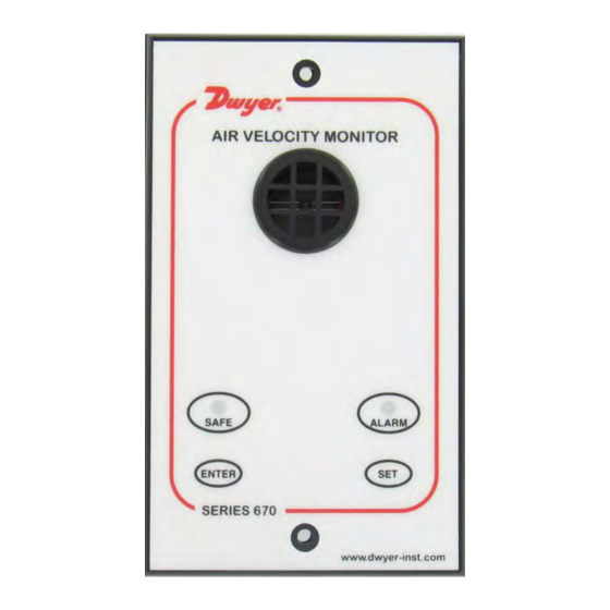
- Page 2 Operator Display Panel Built-in AIRFLOW SENSOR LED indicators Function buttons Calibration. ENTER- also used as Mute button for audible alarm GlobalTestSupply www. .com Find Quality Products Online at: sales@GlobalTestSupply.com...
-
Page 3: Panel Cutout Dimensions
1.67 1.67 [42.55] [42.55] 0.16 [4] 4.96 4.65 [126] [118] 0.16 [4] 2 x FIXING HOLES 2.5 mm DIAMETER FOR 2 x No. 4 3.35 SELF TAPPING [85] SCREWS PROVIDED MOUNTING BRACKET PANEL CUTOUT DIMENSIONS 4.65˝ x 3.35˝ [118 mm x 85 mm] 2-1/64 [51.05] 13/64... -
Page 4: Specifications
SPECIFICATIONS Service: Fume hood face velocity air flow. Alarm Range: 30-400 FPM (0.15-2.0 m/s). Alarm Indication: Red LED & audible alarm. Low Air Velocity Alarm Delay: Fixed 5 s. Display: Visual LEDs: Red: Alarm, Green: Normal. Horn Silence: Yes-temporary and permanent. Accuracy: Face velocity ±10%. Operating Temperature: 55-86°F (13-30°C). Storage Temperature: -40 to 150°F (-40 to 65°C). -
Page 5: Installation Notes
4.0 Fume Hood Installation 1 0 0 m m 1 0 0 m m N o r m a l S a s h 25mm w o r k in g h e i g h t . e g . 5 0 0 m m Female adapter 670 Face Open to the... - Page 6 4.0 Fume Hood Installation STANDARD 25mm SENSOR TUBE MOUNTED ON FRONT OF FC ADAPTER THROUGH INNER SIDE WALL Installation using Duct Connection 1/4 INCH SPIGOTS SPIGOT CONNECTOR FITTED INTO EXTRACT DUCT MOUNTED ON FRONT OF FH CLEAR PVC 1/4 INCH SENSOR TUBE When using the Duct Connection method the 1/4˝...
-
Page 7: Wiring Diagram
Wiring Diagram Flying lead with plug connection for PCB 15 V DC Sash High Micro-switch Sash High (Optional) Proximity switch (Optional) Flying lead with plug connection for PCB Flying lead from Proxy and SM6 airflow switch with plug sensor 12V DC connection for PCB 12V DC Remote... -
Page 8: Night Setback
External Electrical Connections The alarm unit will have the following connection points: Input 1 - Volt free relay input - (close contact to activate the input). This input is configured as: NIGHT SETBACK Output R1 - Volt free relay output - (contact closes on activation). This input is configured as: LOW AIR ALARM Sash High Input - a. ... - Page 9 1.1 General Description All systems comprise of the following components: 1 - 670 Alarm unit 1 - IOM 1 - AC power supply 1 - Vent kit 1 - 24˝ tubing 1 - Mounting bracket w/screws Operator Features - the alarm has the following operator features: Safe LED - Green LED (Not flashing) will be displayed if the airflow is greater than the Low air alarm point. Alarm LED - Red LED (Not flashing) will be displayed if the airflow is lower than the Low air alarm point. Sash High - Red LED (Flashing) will be displayed when the Sash is raised above the max safe working opening. Audible Alarm - The Audible alarm will sound ( can be muted ) in the Air Fail and the Sash High alarm condition. Night Set-back - When the Night Setback input is activated the Audible alarm will be muted and the Green LED will ...
- Page 10 1.2 Alarm Configuration/Calibration The alarm is supplied with a factory configuration. The only part of the configuration that can be changed is the setting for the Sash High timer delay and the percentage figure for the Low Air alarm point when using the two point calibration mode. The alarm has two modes for the calibration of the airflow alarm point. These two modes are selectable via a ‘jumper connection’ on the back of the alarm PCB. The jumper is labeled as CAL and is situated on the edge of the PCB above the Com port. The two calibration modes are: a. Single Point Calibration (with the Jumper connected) - The airflow is reduced mechanically (using balance damper or slowing down the extract fan) to the Low Air alarm point and this air flow is ‘captured’ by the alarm. ...
- Page 11 1.3 Start up When unit is powered up the following sequence of events occur: 1. The 12V DC power is applied to the airflow sensor and the alarm then performs a self test on the functions, LEDs and audible alarm (approx 2 s) and then initiates a delay timer to allow the airflow sensor to stabilize. 2. During the whole of the delay period all alarms and relay outputs are inhibited and the Red & Green LEDs will be permanently ON. 3. At the end of the delay period the unit performs one of two options: a. If the alarm calibration has been previously completed - the unit goes to normal operating mode (Run). b. If the unit has not been calibrated - the Red & Green LEDs will flash on/off and the audible alarm will be muted. It is then possible to press the Enter button for 5 s and go into the calibration mode – (See ‘Quick Start Installation’ below for details of the Calibration procedures). GlobalTestSupply www.
-
Page 12: Low Airflow
1.4 Events / actions Safe airflow • Airflow above alarm level (eg > 80 fpm). • Green LED on. Low airflow • Airflow below alarm level for longer than the low air delay time (5 s). • Red LED on (Not flashing). • Audible alarm sounds (Beep’ on/off every 1 s) - can be muted via Enter pushbutton. • Low air relay R1 operates. Reset - ... - Page 13 2.1 Quick Start Installation Follow the instructions below for installing and commissioning the unit: Before connecting the unit it is important to decide on the type of calibration that is to be used on the installation. The two methods are described in section 1.2 Alarm Configuration/Calibration. 1. Fit the alarm to the Fume Hood using the cut-out details provided with the unit. 2. Plug in the power adapter to a 120V AC power socket and connect the flying lead to the alarm unit - see typical connection diagram on page 6. 3. Power up the unit and wait at least 30 s while the sensor temperature stabilizes. During this time the Red & Green LEDs will both be on (not flashing). If the unit has not been previously calibrated the Red & Green \ LEDs will begin to flash on/off at the end of the 30 s start up time delay but the audible alarm will not sound. If the alarm has been calibrated it will go into normal operation. 4. Calibration: ...
- Page 14 Calibration continued: Two Point Calibration (with CAL jumper on PCB not connected). a. Open the Sash to the normal operating height and adjust the face velocity to the normal operating value using a calibrated instrument to check the value. b. Press and hold the Enter button for 5 s to go into the Calibration mode. This is indicated by both Red and Green LEDS flashing on/off together with the audible alarm sounding (‘Beep’ on/off 4 times every 1 s). c. To initiate the normal airflow (100%) calibration press and hold the ENTER and the SET button at the same time. The unit will then sample the normal airflow for a 5 s period during which time the Green LED goes off and the Red LED flashes on/off. The audible alarm continues to sound during this period and if the sampling is successful ...
- Page 15 2.2 Calibration Notes: 1. The two calibration methods are intended to give the installer two options for calibrating the alarm. 2. Using the Alarm Point Capture method it is necessary to adjust the face velocity on the fume hood using a mechanical damper (or fan speed control if available) to the desired alarm point and this is sampled by the unit. It is then necessary to re-adjust the face velocity back to the normal operating value. This method produces a very accurate alarm point at a fixed value but involves getting access to the ductwork or fan speed controller. 3. The second method of Two Point Capture is slightly more involved but does not require any access to the ...
-
Page 16: Maintenance
MAINTENANCE Upon final installation of the Series 670 Hood Monitor, no routine maintenance is required. The Series 670 is not field serviceable and should be returned if repair is needed (field repair should not be attempted and may void warranty). Be sure to include a brief description of the problem plus any relevant application notes. Contact customer service to receive a return goods authorization number before shipping. ©Copyright 2017 Dwyer Instruments, Inc. Printed in U.S.A. 11/17 FR# 443751-00 Rev. 1 GlobalTestSupply www. .com Find Quality Products Online at: sales@GlobalTestSupply.com...
Need help?
Do you have a question about the 670 Series and is the answer not in the manual?
Questions and answers