Advertisement
Quick Links
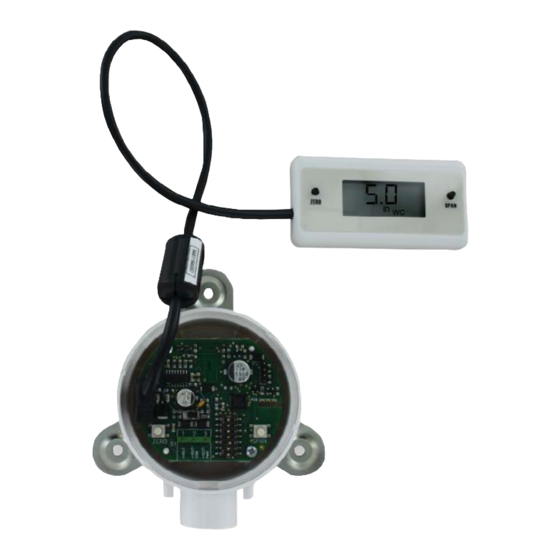
Model A-435-A Remote Display Tool
Specifications - Installation and Operating Instructions
An option for Magnesense
II Differential Pressure Transmitter models that do not
®
have a display is to use a Model A-435-A Remote Display Tool which can plug into
the connector shown in Figure 1. The remote display tool has two buttons that function
identically to the buttons on the PCB.
CALIBRATION
Once the zero or span calibration button is released, there is a 5
NOTICE
second delay before the change takes effect. This delay is used to
prevent stress related offsets on the lower ranges.
The security level that is set in the Programming Menu Section
NOTICE
of the manual will determine which calibrations, if any, may be
adjusted by the user.
Zero Calibration
In order to apply the zero calibration, vent both pressure ports to atmosphere or apply
equal pressure to both ports then press the zero button for 3 seconds. The display will
read 2Ero and then sequence back to the home display. If the current reading is not
close enough to zero (±2%), the operation will fail and FAIL will be displayed.
DWYER INSTRUMENTS, INC.
P.O. BOX 373 • MICHIGAN CITY, INDIANA 46360, U.S.A.
SPAN Calibration
The span calibration can only be adjusted after completing the zero calibration. It
must be completed within 5 minutes of the last zero calibration. The span calibration
button will be ignored until the zero calibration is completed. Apply the maximum full-
scale pressure value, indicated by the DIP switch setting, to the positive pressure port
(i.e. the pressure value corresponding to 20 mA, 5 V, or 10 V depending on selected
output). Press and hold the span button for 3 seconds. The display will read SPAn and
then sequence back to the home display. If the span calibration is attempted before
adjusting the zero calibration, the FAIL error message will flash on the display. A failure
will also occur if the span operation is performed too closely to the zero point pressure.
Display Error Messages
ouEr = The applied pressure is greater than the maximum span value causing an Over
Range Error.
UndEr = The applied pressure is less than the minimum span value causing an Under
Range Error.
FAiL = When the span or zero buttons are pressed, the pressure value is out of the
range to allow a correct setting. This may be due to a sensor failure or incorrect
pressure being applied.
Err1 = The sensor is damaged.
-rErr = Negative display value too low to display.
PROGRAMMING MENUS
Home Menu
During normal operation, the display will be in the Home Menu and will display the
current measured pressure and the engineering units.
Menu Access Security
While in the Home Menu, press and hold the Zero and Span buttons simultaneously
until SECUr appears on the display in order to access the other programming menus.
Upon releasing the buttons, the display will indicate the current security level.
If the current security level is the security level desired (i.e. Security Level 0), press
and hold the span button for three seconds to enter the Pressure, Velocity, or Air Flow
Menu.
If the security level is not the desired level, the security level can be changed
temporarily to a lower security level or permanently to a higher level of security by
pressing the zero button. A security code will be shown on the display and it can be
changed to one of the codes listed in the below table. The span button chooses which
digit and the zero button increments the value of that digit. Pressing and holding the
span button will store the value.
Access
Security
Level
Setting
View Menu Edit Menu
0
000
Yes
1
111
Yes
2
222
No
3
333
No
The level of access to the programming menus and the calibration is limited based on
the security level. The above table details the level of access for each security level.
Phone: 219-879-8000
Fax: 219-872-9057
Bulletin P-A-435-A
Span Zero
Yes
Yes
Yes
No
No
Yes
No
No
Yes
No
No
No
www.dwyer-inst.com
e-mail: info@dwyermail.com
Advertisement

Related Manuals for Dwyer Instruments A-435-A


Summary of Contents for Dwyer Instruments A-435-A
- Page 1 SPAN Calibration ® have a display is to use a Model A-435-A Remote Display Tool which can plug into The span calibration can only be adjusted after completing the zero calibration. It the connector shown in Figure 1. The remote display tool has two buttons that function must be completed within 5 minutes of the last zero calibration.
-
Page 2: Maintenance/Repair
(POH) can be adjusted to any pressure between the lowest dip switch range Upon final installation of the A-435-A, no routine maintenance is required. The A-435-A to the highest dip switch range. If the dip switch settings are preferred over manually is not field serviceable and it is not possible to repair the unit. -
Page 3: Menu Flow Chart
APPENDIX III Quick Start Guide MENU FLOW CHART BUTTON BUTTON PRESS PRESS LEGEND LEGEND = PRESS PRESS ZERO ZERO BUTTON BUTTON ZERO ZERO = PRESS PRESS SPAN SPAN BUTTON BUTTON SPAN SPAN = PRESS PRESS AND AND HOLD HOLD ZERO ZERO BUTTON BUTTON ZERO... - Page 4 PRESSURE PRESSURE MODE MODE MENU MENU FROM FROM AVERAGING AVERAGING MENU MENU ADJUST ADJUST PRESSURE PRESSURE OUTPUT OUTPUT HIGH HIGH " " AdJ P P FROM FROM MENUS MENUS SPAN SPAN PoH = DIP DIP SWITCH SWITCH FULL FULL SCALE SCALE SETTING SETTING UPON...
- Page 5 FLOW FLOW MODE MODE MENU MENU FROM FROM AVERAGING AVERAGING MENU MENU UNITS UNITS SELECTED SELECTED UnIt UnIt UnIt UnIt SELECTED SELECTED UNITS UNITS BY DIP DIP SWITCH SWITCH DISPLAYED DISPLAYED SETTING SETTING SPAN ADJUST ADJUST DISPLAY DISPLAY UPON UPON RELEASE RELEASE SPAN SPAN...
- Page 6 __________________________________________________________________________________________________________________________________________ __________________________________________________________________________________________________________________________________________ __________________________________________________________________________________________________________________________________________ __________________________________________________________________________________________________________________________________________ __________________________________________________________________________________________________________________________________________ __________________________________________________________________________________________________________________________________________ __________________________________________________________________________________________________________________________________________ __________________________________________________________________________________________________________________________________________ ©Copyright 2020 Dwyer Instruments, Inc. Printed in U.S.A. 10/20 FR# 444125-00 Rev. 3 DWYER INSTRUMENTS, INC. Phone: 219-879-8000 www.dwyer-inst.com P.O. BOX 373 • MICHIGAN CITY, INDIANA 46360, U.S.A. Fax: 219-872-9057 e-mail: info@dwyermail.com...
Need help?
Do you have a question about the A-435-A and is the answer not in the manual?
Questions and answers