Table of Contents
Advertisement
Quick Links
Plane-Power Aero
2900 Selma Highway
Montgomery, AL 36108, USA
Tel: 334-386-5400 Fax: 334-386-5410
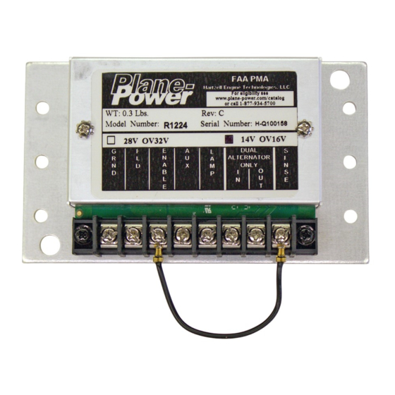
R1224 REGULATOR
Page: i
24-20-01
© 2018 - Hartzell Engine Technologies - All rights reserved
INSTALLATION
INSTRUCTIONS
12-1001
P/N
R1224 Regulator
Installation Instructions
Rev. L: 09 Sept. 2018
12-1001
Advertisement
Table of Contents

Subscribe to Our Youtube Channel
Related Manuals for Plane-Power R1224

Summary of Contents for Plane-Power R1224
- Page 1 Plane-Power Aero R1224 Regulator 2900 Selma Highway Montgomery, AL 36108, USA Installation Instructions Tel: 334-386-5400 Fax: 334-386-5410 R1224 REGULATOR INSTALLATION INSTRUCTIONS 12-1001 Page: i 24-20-01 12-1001 © 2018 - Hartzell Engine Technologies - All rights reserved Rev. L: 09 Sept. 2018...
-
Page 2: Record Of Revisions
R1224 Regulator Installation Instructions RECORd Of REvISIONS Revision Date Page Description 09/08/14 First release of Drawing No. 12-1001 into Hartzell Engine Technologies Design Data. 09/08/14 Updated Master Drawing No. 12-1001 Title Block from Plane- Power, LTD to Harzell Engine Technologies, LLC... -
Page 3: Table Of Contents
R1224 Regulator Installation Instructions TAbLE Of CONTENTS Record of Revisions .............................ii Table 1 - Supplement Information Reference ...................1-1 Figure 1 - Drawing No. 12-1001 Rev. K ....................1-4 Section 1 - Installation Instructions ......................1-5 Single Engine ............................1-5 Multi-Engine...............................1-6 Maintenance Instructions ..........................1-6 Section 2 - Installation Guides ........................2-1... -
Page 4: Section 1 - Installation Instructions
Installation Instructions Some aircraft models were manufactured with different regulators and different wiring arrangements, plugs, etc. Some installations can be accomplished using the basic R1224 Installation Instructions in (12-1001 pages 2, & 3). Supplemental information for individual regulators is provided where necessary. - Page 5 R1224 Regulator Installation Instructions Table 1 - Supplement Information Reference (cont’d) Supplement Note: All twin engines must replace both regulators OEM Part Number PP Part# Information Cessna Aircraft Company (cont’d) 337F, 337G, 337H, FT337P, T337F, T337G, T337H, C611002-0102, C611002-0105 R1224...
- Page 6 R1224 Regulator Installation Instructions Table 1 - Supplement Information Reference (cont’d) Supplement Note: All twin engines must replace both regulators OEM Part Number PP Part# Information Piper (cont’d) PA-31, PA-31-300, PA-31-325, PA-31-350, PA-23, PA-23, PA-23-160, PA-23-235, PA-23-250, PA-E23- Piper 550 390, 550 393, 84199-...
- Page 7 R1224 Regulator Installation Instructions Page: 1-4 24-20-01 12-1001 © 2018 - Hartzell Engine Technologies - All rights reserved Rev. L: 09 Sept. 2018...
-
Page 8: Single Engine
If an ALTERNATOR out lamp is installed in the aircraft and is to be actuated by the R1224/R1224B regulator Connect the negative wire of the lamp to the LAMP terminal of the R1224/R1224B regulator. -
Page 9: Multi-Engine
R1224 Regulator Installation Instructions multi-Engine For both regulators, perform steps A thru J of the Single Engine procedure above. Choose one regulator as the Master. It can be either. Connect the OUT terminal of the Master Regulator to the IN terminal of the other Regulator. -
Page 10: Section 2 - Installation Guides
Connect the Black wire to R1224 #1 (GND). Connect the Black wire to R1224 #1 (GND). Connect the yellow (Field) wire to R1224 #2 Connect the Blue (Field) wire to R1224 #2 (Field). (Field). Connect the Red (Power) wire to R1224 #3 Connect the Red (Power) wire to R1224 (Enable). -
Page 11: Guide D
#8 (SENSE) and #3 (ENABLE). Jumper R1224 #3 (Enable) to #4 (AUX). Connect the Orange (Sense) wire to R1224 #8 For R1224 Rev B and earlier: Insulate the end of (SENSE) the A (Sense) wire and stow it safely. -
Page 12: Guide E
Guide f There is a round connector on these Beechcraft regulators. Use two R1224 regulators set for 14V. Use the 12-1021 A round plug on a cable is plugged into the connector on the adaptor plate for mounting (which can be purchased from regulator. -
Page 13: Guide G
Ensure that the R1224B internal jumpers are set properly for the aircraft voltage. See Plane-Pow- Remove old regulator. er R1224 Installation Drawing 12-1001. Ensure that the R1224 jumpers are set for 14V. Mark the wires on the Lamar regulators and See Plane-Power R1224 Installation Drawing disconnect them. -
Page 14: Guide J
(which can be purchased from Remove old regulator. Plane-Power). Ensure regulator jumpers are set to match aircraft battery voltage (12V or 24V). Ensure that the R1224 jumpers are set for 28V. See Plane-Power R1224 Installation Drawing Ensure that the factory installed jumper between 12-1001. -
Page 15: Guide L
Cut the terminals off the end of these wires and install new ring lugs provided with the R1224B Cut the terminals off the end of these wires and regulators. install new ring lugs provided with the R1224 regulator. Replace the regulators: Remove the Lamar regulators from the aircraft. -
Page 16: Guide M
The R1224 has internal over voltage protection, so the Interav over voltage relay is no longer needed. Ensure that the R1224 jumpers are set for 14V. See Plane-Power R1224 Installation Drawing 12-1001. Add a jumper between SENSE and AUX on both R1224B regulators.
Need help?
Do you have a question about the R1224 and is the answer not in the manual?
Questions and answers