
Subscribe to Our Youtube Channel
Related Manuals for Plane-Power R1224

Summary of Contents for Plane-Power R1224
- Page 1 R1224 Regulator Installation Instruction R1224 REGULATOR INSTALLATION INSTRUCTIONS 12-1001 12-1001 24-30-01 Rev. M: 01 Dec. 2021 Page: i © 2021 - Hartzell Engine Technologies - All rights reserved...
- Page 2 R1224 Regulator Installation Instruction Copyright © 2021 Hartzell Engine Technologies LLC All rights reserved. No part of this publication may be reproduced, stored in a retrieval system, or transmitted, in any form or by any means, electronic, mechanical, photocopying, recording, or otherwise, without the prior written permission of Hartzell Engine Technologies LLC.
- Page 3 Revised 09/08/14 First release of Drawing No. 12-1001 into Hartzell Engine Technologies Design Data. 09/08/14 Updated Master Drawing No. 12-1001 Title Block from Plane-Power, LTD to Harzell Engine Technologies, LLC. 11/18/14 Changed Instruction for Continued Airworthiness to Maintenance Instructions. 02/01/17 Added website reference to Master Drawing No.
- Page 4 R1224 Regulator Installation Instruction THIS PAGE INTENTIONALLY LEFT BLANK 24-30-01 12-1001 Rev. M: 01 Dec. 2021 Page: iv © 2021 - Hartzell Engine Technologies - All rights reserved...
-
Page 5: Table Of Contents
Description ............................2-1 Basic Component Description .......................2-1 Theory of Operation ........................2-1 SECTION 3 - TROUBLESHOOTING ......................3-1 General ............................3-1 Procedure ............................3-1 R1224 Regulator Troubleshooting ....................3-1 SECTION 4 - CHECK ..........................4-1 General ............................4-1 Inspection Checks .........................4-1 SECTION 5 - TESTING ..........................5-1 General ............................5-1 SECTION 6 - INSTALLATION ........................6-1... - Page 6 R1224 Regulator Installation Instruction Regulator Installation Guide-A ..................... 6-7 A. General ............................6-7 Regulator Installation Guide-B ..................... 6-7 A. General ............................6-7 Regulator Installation Guide-C ..................... 6-8 A. General ............................6-8 Regulator Installation Guide-D ..................... 6-8 A. General ............................6-8 Regulator Installation Guide-E ..................... 6-9 A.
- Page 7 R1224 Regulator Installation Instruction Thank you for purchasing a PlanePower* R1224 regulator. We encourage you to read this instruction thoroughly. It contains a wealth of information about how to properly install and maintain your regulator so that it may give you many years of safe and reliable service.
-
Page 8: Airworthiness Limitations
R1224 Regulator Installation Instruction AIRWORTHINESS LIMITATIONS General Information CAUTION: THE AIRWORTHINESS LIMITATIONS HEREIN ARE THOSE MANDATED BY HARTZELL ENGINE TECHNOLOGIES. THESE LIMITATIONS ARE THE MINIMUM REQUIRED TO MEET CONTINUED AIRWORTHINESS BUT MAY BE SUPERSEDED BY MORE STRINGENT REQUIREMENTS AS PUBLISHED BY THE FAA, AIRCRAFT, ROTORCRAFT OR OTHER MANUFACTURERS THAT USE THESE COMPONENTS IN THEIR APPLICATIONS. -
Page 9: Life Limits
B. Additions of, or changes to, any life limit for alternator components will be noted in the Airworthiness Limitation Revision Log. C. Life Limits R1224 series regulators and their component parts affected by this instruction currently do not have any life limited parts. There are no new (or additional) Airworthiness Limitation associated with this equipment. -
Page 10: Section 1 - Introduction
R1224 Regulator Installation Instruction SECTION 1 - INTRODUCTION 1.1 General Information WARNING: IMPROPER OR UNAUTHORIZED APPLICATIONS OF THE INFORMATION CONTAINED IN THE INSTRUCTION MAY RENDER THE AIRCRAFT OR THE COMPONENT UNAIRWORTHY AND RESULT IN LOSSES, DAMAGES, OR INJURY TO THE USER. -
Page 11: General Specification (Instruction)
Principle units of measure used in this instruction are U.S. units with International System of Units (SI) in parentheses. B. The R1224, R1224B, and R1224J regulator models are considered herein. C. All aircraft, rotorcraft, or engine applications are limited to the holder of the TC, STC, PMA or TSO and only at the date of that document publication or revision. -
Page 12: Abbreviations
R1224 Regulator Installation Instruction B. U.S. Units Foot Inch Pound lbf ∙ in Pound-force inch lbf ∙ ft Pound-force foot Degree Fahrenheit C. Multiplying Prefixes μ Micro Milli Kilo Mega Pico Abbreviations A. The abbreviations given below are used in this instruction: (upper or lower case) -
Page 13: Definitions
R1224 Regulator Installation Instruction Definitions A. This paragraph defines the warnings and notifications used in this instruction. WARNINGS place critical attention to use of tools, materials, procedures, or limitations, which must be followed without deviation to avoid injury to the technician or other persons. CAUTIONS place immediate attention to use of tools and procedures which must be followed to avoid injury, damage to equipment and/or facilities. -
Page 14: Serial Number Identification
R1224 Regulator Installation Instruction Serial number Identification Year Code Month Code Batch Code Example above: 2021, May, first unit of the month (batch). The year code advances one letter in alphabetical order for each succeeding year. 1.10 Warranties A. Hartzell Engine Technologies LLC (HET) offers a Limited warranty with each new, overhauled, or rebuilt regulator assembly or component (parts) it sells through it’s distribution system. - Page 15 R1224 Regulator Installation Instruction THIS PAGE INTENTIONALLY LEFT BLANK 24-30-01 12-1001 Rev. M: 01 Dec. 2021 Page: 1-6 © 2021 - Hartzell Engine Technologies - All rights reserved...
-
Page 16: Section 2 - Description Of Operation
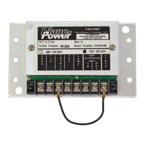
Description A. The Plane Power R1224 Voltage Regulator is a solid-state voltage regulator with over-voltage protection, field short (over current) protection, and reverse battery protection. The R1224 regulator is designed to be set up for 14 or 28 volt configurations. - Page 17 R1224 Regulator Installation Instruction 5A Typical Alternator Figure 2-1 - Typical R1124 Wiring Diagram 24-30-01 12-1001 Rev. M: 01 Dec. 2021 Page: 2-2 © 2021 - Hartzell Engine Technologies - All rights reserved...
-
Page 18: Section 3 - Troubleshooting
The overall objective of troubleshooting is to find the cause of trouble and take corrective action to prevent a recurrence. This section provides general troubleshooting procedures for the R1224 regulator assembly for unscheduled maintenance. It gives procedures to follow to determine the best course of action prior to replacement. - Page 19 ALTERNATOR CB 1 AMP FUSE/CB R1224 TS Diagram (Typical) Verify the R1224 Regulator is wired per applicable guide in Section 6. If no guide is present for specific application, use the diagram found on this page. Refer to seciton 6 of this document Call or email TECH SUPPORT for further instructions Phone: +1.334.386.5400, option 2...
-
Page 20: Section 4 - Check
R1224 Regulator Installation Instruction SECTION 4 - CHECK General A. This section defines the various checks and inspections needed to assure reliable and safe operation of the alternator while in service. They are listed in hours time in service (TIS) or in calendar time, whichever is applicable and are the first to occur when offered a choice. - Page 21 R1224 Regulator Installation Instruction THIS PAGE INTENTIONALLY LEFT BLANK 24-30-01 12-1001 Rev. M: 01 Dec. 2021 Page: 4-2 © 2021 - Hartzell Engine Technologies - All rights reserved...
-
Page 22: Section 5 - Testing
R1224 Regulator Installation Instruction SECTION 5 - TESTING General Perform all tests and checks in accordance with appropriate aircraft/engine maintenance manuals and service instructions. Alternatively, Table 3.1 of Section 3 may be utilized to test the regulator for proper function. - Page 23 R1224 Regulator Installation Instruction THIS PAGE INTENTIONALLY LEFT BLANK 24-30-01 12-1001 Rev. M: 01 Dec. 2021 Page: 5-2 © 2021 - Hartzell Engine Technologies - All rights reserved...
-
Page 24: Section 6 - Installation
Some aircraft models were manufactured with different regulators and different wiring arrangements, plugs, etc. Some installations can be accomplished using the basic R1224 Installation Instructions in paragraph 6.2 and 6.3 , this section. Supplemental information for individual regulators is provided where necessary. To account for model differences follow the steps below to ensure proper replacement: Find your aircraft model and OEM P/N in Table 6-1. - Page 25 R1224 Regulator Installation Instruction Note: All twin engines must replace Plane Power Supplement OEM Regulator P/N both regulators Regulator P/N Information Cessna Aircraft Company 182, 182A, 182B, 182C, 182D, 182E, 182F, 182G, 210, 210A, 210B, 210-5 (205), 185, 185A, 185B, 185C, 180,...
- Page 26 R1224 Regulator Installation Instruction Note: All twin engines must replace Plane Power Supplement OEM Regulator P/N both regulators Regulator P/N Information LAVIA PA-25, PA-25-235, PA25-260, PA-25, PA-25-235, PA-28- InterAv 625-61623 R1224 Guide M Mooney M20, M20A, M20B, M20C, M20D, M20E, M20F, M20G...
- Page 27 R1224 Regulator Installation Instruction Note: All twin engines must replace Plane Power Supplement OEM Regulator P/N both regulators Regulator P/N Information True Flight Holdings, LLC C6FF-10316BA, D4FF-10316- AA-5, AA-5A, AA-5B R1224 Guide D Prestolite FVR-4004, AA-1B LW- 11357, Wico X17990,...
-
Page 28: Single Engine
A. Installation Remove existing regulator and solid-state over-voltage module (if installed). (2) Install the regulator (R1224/R1224B/R1224J) in same location as regulator being replaced. If mounting holes do not align, add mounting holes as required using acceptable methods, techniques and practices such as those found in AC 43-13-1B and AC 43-13-2B. -
Page 29: Regulator Installation Guide-A
If applicable for LAMP function, connect a locally manufactured jumper between R1224 #3 (Enable) & #4 (Aux). For R1224 Rev C and later (Fig. 6-1): Remove jumper between #8 (Sense) and #3 (Enable). Connect the A (Sense) wire to R1224 #8 (Sense). -
Page 30: Regulator Installation Guide-C
For R1224 Rev C and later: Remove jumper between #8 (SENSE) and #3 (ENABLE). Connect the Orange (Sense) wire to R1224 #8 (SENSE). (10) Insulate the end of the White (OV Lamp) wire and stow it safely. (The R1224 indicates Over Voltage and Low Voltage on a common lamp connected to R1224 #5.) (11) Adjust voltage as necessary with engine running and alternator enabled. -
Page 31: Regulator Installation Guide-E
R1224 Regulator Installation Instruction For R1224 Rev B and earlier: Insulate the end of the A (Sense) wire and stow it safely. For R1224 Rev C and later: Remove jumper between #8 (SENSE) and #3 (ENABLE). Connect the Orange (Sense) wire to R1224 #8 (SENSE) Adjust voltage as necessary with engine running and alternator enabled. -
Page 32: Regulator Installation Guide-F
Cut the wires close to the regulator case of the Electrodelta or Wico regulators and crimp one appropiate ring lug with the R1224 on each Red and Blue (or Yellow) wire. Remove remaining wires or insulate the ends. -
Page 33: Regulator Installation Guide-H
R1224 Regulator Installation Instruction 6.11 Regulator Installation Guide-H A. General Use 2 R1224B as the mounting holes match the Lamar regulators. Both regulators must be replaced. Ensure that the R1224B internal jumpers are set properly for the aircraft voltage (Fig 6-1). -
Page 34: Regulator Installation Guide-I
Ensure that the factory installed jumper between SENSE and ENABLE is in place. B. Prepare the installation Cut the wires at the regulator body and new ring lugs provided with the R1224 regulator. Unplug the wire connector from the aircraft plug. -
Page 35: Regulator Installation Guide-J
Remove old regulator. Ensure that the R1224 jumpers are set for 28V. See Plane-Power R1224 Installation Drawing 12-1001. Install R1224 using the 12-1021adaptor plate. Put the large ring lug on the black wire under one of the mounting bolts. -
Page 36: Regulator Installation Guide-L
Add a jumper between ENABLE and AUX. B. Prepare the installation: Cut the terminals off the end of these wires and install new ring lugs provided with the R1224 regulator. C. Replace the regulator Remove the FORD-type regulator from the aircraft. -
Page 37: Regulator Installation Guide-M
Remove Interav regulator and over voltage relay. The R1224 has internal over voltage protection, so the Interav over voltage relay is no longer needed. Ensure that the R1224 jumpers are set for 14V (Fig. 6-1). Add a jumper between SENSE and AUX on both R1224B regulators. -
Page 38: Regulator Installation Guide-N
R1224 Regulator Installation Instruction 6.17 Regulator Installation Guide-N A. General Replacement of Jasco J12M20SP (12V) or J12M24SP (24V) regulators. B. Prepare the replacement regulator Use R1224J, ensure regulator jumpers are set to match aircraft battery voltage (Fig. 6-1). Add jumper between ENABLE and AUX terminals (Regulator side only). - Page 39 R1224 Regulator Installation Instruction THIS PAGE INTENTIONALLY LEFT BLANK 24-30-01 12-1001 Rev. M: 01 Dec. 2021 Page: 6-16 © 2021 - Hartzell Engine Technologies - All rights reserved...
Need help?
Do you have a question about the R1224 and is the answer not in the manual?
Questions and answers