Advertisement
Instruction Manual
CANsmart™ Controller
DNL.WHS.24700
Husqvarna Norden Series
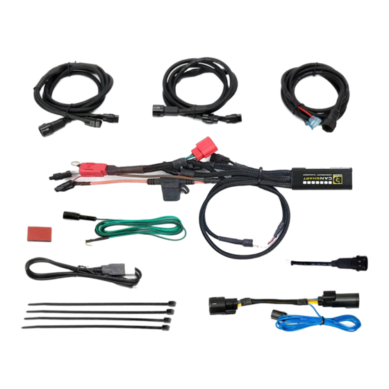
What's In The Box?
(c)
(g)
(f)
Kit Contents
(a) CANsmart™ Controller (DNL.WHS.111)...................................Qty 1
(b) 5ft Horn Extension (DNL.WHS.066)........................................Qty 1
(c) 5ft LED Light Extension (DNL.WHS.018)..................................Qty 2
(d) Brake Light Pigtail (DNL.WHS.067).........................................Qty 1
(e) Horn Input Harness..............................................................Qty 1
(e)
(h)
DENALIELECTRONICS.COM
DENALIELECTRONICS.COM
Instruction Rev00
Thank you for choosing DENALI
We know you would rather be riding your bike than wrenching on it, so we go the extra
mile to make sure our instructions are clear and as easy to understand as possible. If
you have any questions, comments, or suggestions don't hesitate to give our experts
a call at 401.360.2550 or visit WWW.DENALIELECTRONICS.COM
Please Read Before Installing
DENALI products should always be installed by a qualified motorcycle technician. If
you are unsure of your ability to properly install a product, please have the product
installed by your local motorcycle dealer. DENALI takes no responsibility for damages
caused by improper installation. Caution: When installing electronics it is extremely
important to pay close attention to how wires are routed, especially when mounting
products to the front fender, front fork, or fairing of your motorcycle. Always be sure
to turn the handlebars fully left, fully right, and fully compress the suspension to
ensure the wires will not bind and have enough slack for your motorcycle to operate
properly.
Installation Tips
We strongly recommend using medium strength liquid thread locker on all screws and
bolts. It is also important to ensure that all hardware is tightened to the proper torque
specifications as listed in your owner's manual. For included accessory hardware
please refer to the default torque specifications provided below. Inspect all hardware
after the first 30 miles to ensure that proper torque specifications are maintained.
Bolt Size
in-lbs
M3
10.0 in-lbs
23.0 in-lbs
M4
M5
44.5 in-lbs
M6
78.0 in-lbs
M8
-
M10
-
M12
-
Hardware Sizing Guide
Not sure what size bolt you have? Use this ruler to measure screws, bolts, spacers, etc.
Remember, the length of a screw or bolt is measured from the start of the "mounting
surface" to the end of the screw, so only include the screw head when measuring
countersunk screws.
0
10
20
30
40
mm
0
1
in
(b)
(d)
(i)
(f) Zip Tie...............................................................................Qty 4
(g) Adhesive Dual Lock..............................................................Qty 1
(h) USB to Micro USB Programming Cable....................................Qty 1
(i) Headlight Input Harness........................................................Qty 1
ft-lbs
Nm
-
1.0 Nm
-
2.5 Nm
3.5 ft-lbs
5.0 Nm
6.5 ft-lbs
9.0 Nm
13.5 ft-lbs
18.0 Nm
30.0 ft-lbs
41.0 Nm
52.0 ft-lbs
71.0 Nm
50
60
70
80
90
2
3
(a)
Advertisement
Table of Contents

Subscribe to Our Youtube Channel
Related Manuals for Denali CANsmart DNL.WHS.24700


Summary of Contents for Denali CANsmart DNL.WHS.24700
- Page 1 401.360.2550 or visit WWW.DENALIELECTRONICS.COM Please Read Before Installing DENALI products should always be installed by a qualified motorcycle technician. If you are unsure of your ability to properly install a product, please have the product installed by your local motorcycle dealer. DENALI takes no responsibility for damages caused by improper installation.
-
Page 2: Device Overview
CANsmart™ Accessory Manager Software. The four circuits are pre-programmed to connect and independently control two sets of DENALI 2.0 lights, a SoundBomb horn, and our B6 auxiliary brake light. However, our Circuit Function Selector in the CANsmart software will let you run any accessory of your choice on any of the four circuits. -
Page 3: Connecting Accessories
In the default configuration, the circuit for Light Set One is the longest red Step Three: Plug the DENALI Light Pods into the female 3-pin connec- lead, the shortest white lead is for Light Set Two. Both circuits are designed tors of the Extension-Splitter. - Page 4 Step Three: Plug the spade connectors of the Horn Extension into the Step Four: Plug the horn positive wire into the piggy back terminal on DENALI SoundBomb Horn. The Green wire connects to the positive (+) the Horn Input Harness.
- Page 5 Wiring Adapter 3.4 - Brake Light - (Yellow Circuit) Step One: Route the harness of the DENALI B6 Brake Light from the rear of your motorcycle toward the CANsmart™ Controller. Step Two: Plug the Brake Light Pigtail into the connector on the DENALI B6 Brake Light.
-
Page 6: Software Overview
Software Overview DENALIELECTRONICS.COM DENALIELECTRONICS.COM Turn Signal Not Available (Norden 901) Turn Signal Not Available (Norden 901) 4.1 - Circuit Function Selector The Circuit Function Selector in the CANsmart software will let you run any accessory of your choice on any of the four circuits. Click on a circuit icon to open the drop down menu and make your selection from the list of available circuit functions. - Page 7 Software Overview ( continued) DENALIELECTRONICS.COM DENALIELECTRONICS.COM Not Available 4.3 - Auxiliary Lights Two (Pair or Split) Available settings include “Strobe when horn active”, “Strobe on flash to pass”, as well as “Modulation”. “Three-Wire dimming mode” can be turned off to properly dim LED lights which do not have a dedicated 3rd dimming wire.
- Page 8 Software Overview (continued) DENALIELECTRONICS.COM DENALIELECTRONICS.COM Not Available 4.7 - Run/Brake/Turn The run/brake/turn signal circuit enables the addition of an auxiliary run brake turn signals complete with flash patterns, all without having to tap into the bikes factory turn signal or brake harness. 4.8 - Heated Gear 4.8 - Heated Gear The heated gear circuit enables heated gear to work in conjunction with the motorcycles factory heated grip settings.
- Page 9 Software Overview (continued) DENALIELECTRONICS.COM DENALIELECTRONICS.COM 4.9 - Where To Download The Software The CANsmart™ Accessory Manager Software is available for both Windows and Mac operating systems. To download your copy please visit WWW.DENALIELECTRONICS.COM/PAGES/CANSMART-SOFTWARE CANsmart Programming Cable 54.10- Connecting The Device To The Software Step One: Remove the protective cap from micro USB port on the end of the CANsmart™...
-
Page 10: Troubleshooting Guide
Solid Red & Solid Green Device has been deactivated Return to DENALI for analysis. Please send log files info@DENALIelectronic.com for analysis by DENALI. Data/configuration fault. (missing CAN bus Check that the correct CAN bus connector was used. If the problem persists please send log files to Flashing Red &...
Need help?
Do you have a question about the CANsmart DNL.WHS.24700 and is the answer not in the manual?
Questions and answers