ABB VM1 Instruction Manual
Vacuum circuit-breaker
Hide thumbs
Also See for VM1:
- Installation and service instructions manual (60 pages) ,
- Instruction manual (56 pages) ,
- Manual (52 pages)
Table of Contents
Advertisement
Quick Links
Advertisement
Table of Contents

Subscribe to Our Youtube Channel
Related Manuals for ABB VM1


Summary of Contents for ABB VM1
- Page 1 Vacuum circuit-breaker Instruction manual BA 504/02 E...
- Page 2 Your safety first – always! That's why our instruction manual begins with these recommendations: • Only install switchgear and/or switchboards in enclosed rooms suitable for electrical equipment. • Ensure that installation, operation and maintenance are carried out by specialist electricians only. •...
-
Page 3: Table Of Contents
Interlocks / protection against maloperation 7.6.2 Auxiliary materials and lubricants (for C.B. on withdrawable parts) Application of the X-ray regulations 3.4.2 Interlocks for VM1 withdrawable parts Figures 3.4.2.1 Interlocks when using ABB withdrawable Technical data assemblies are used 10.1 Technical data, general 3.4.3... -
Page 4: General
Operating conditions 1.3.1 Normal operating conditions General Design to VDE 0670, part 1000, "Common The vacuum circuit-breakers of type VM1 are inten- specifications for high-voltage switchgear and ded for indoor installation in air-insulated switch- controlgear standards“ and IEC publication 60694, gear. -
Page 5: Structure
2.1.2 Storage capacitor Structure (Figures 9/16, 9/18 b and 9/28) Structure of the operating mechanism The energy for operation of the circuit-breaker is (Figures 9/13 to 9/16 and 9/28) stored electrically in a capacitor. Circuit-breakers for breaking currents of 31.5 kA and above are The operating mechanism is of the magnetic type. -
Page 6: Basic Structure Of The Circuit-Breaker
Basic structure of the circuit-breaker on and -Y2 (OFF) (see also sections 10.1.1a and 6.2). withdrawable part The breaker can be operated locally by pressing push-buttons 3 and 4. (Figures 9/9 to 9/12, 9/19 and 9/24) In the closing process, the armature motion acts The withdrawable part, which can be moved direct via lever shaft 18 on the moving contact 24.1 manually or by a motor if fitted, consists of a steel... -
Page 7: Extended Functions In The Full Version
-Y0. figure 9/18a. Wiring diagrams for C.B. on withdrawable part If no voltage is applied to -Y4, the VM1 cannot be closed. (Figures 10/14 to 10/17 and 9/17) • The wiring diagrams, shown in figures 10/14 to... -
Page 8: Quenching Principle Of The
1.) The VM1 can only be closed via input -Y3 when jected to a routine test in accordance with a voltage of 24 V to 240 V AC/DC is applied to VDE 0670, part 1000 or IEC publication 60694, input -Y1 (electrical closing lock-out). -
Page 9: Packaging
Packaging • Room temperature which does not fall below –25°C. The switching devices are mounted individually on a wooden pallet and sealed in film and/or packed in • Do not remove or damage the packaging. cardboard for delivery. • Unpackaged devices: Packaging for overseas shipment: –... -
Page 10: Commissioning/Operation
• Properly refit all covers, etc., removed during Recommended assembly and testing processes. tightening torque • Connect the supply voltage (Figures 10/6 and 10/14 to 10/17). Input -Y4 : ”OFF command” (closed-circuit shunt release) and input -Y1: Lubricant ”Closing lock-out” (closed-circuit shunt release) Thread Without Oil or... -
Page 11: Manual Insertion From The Test/ Disconnected Position To The Service Position
Note: Note: Withdrawable parts with blocking magnet -Y0 may In order to avoid damage to the operating not be forcibly moved during power failures. In mechanism, use the original hand crank only. such a case they are blocked in the service and test –... -
Page 12: Circuit-Breaker Operation
Manual emergency opening is possible and short-circuit currents. beyond these times. The typical life expectancy of a VM1 vacuum Insert emergency manual operation lever 28 circuit-breaker is determined by: into socket 8 in the front plate and turn it anti- clockwise to open the circuit-breaker. -
Page 13: Inspection And Functional Testing
Maintenance work may only be performed by fully side. trained personnel, observing all the relevant safety regulations. It is recommended that ABB after- If an irregular condition is found, appropriate sales service personnel should be called in, at least maintenance work is to be initiated. -
Page 14: Servicing
(see the section on repairs). Dismantling and replacement of the breaker poles • The interlock conditions and the ease of should only be performed by the ABB after-sales movement of the withdrawable assembly are to service or adequately trained specialist staff, in be checked as described under “Repair”. -
Page 15: Repair
• Earth all poles of the VM1 circuit-breaker on one – Fit the contact system back to front on the side. thin end of arbor 39, and slide it forwards onto the thicker part of the shank. • Connect the earthed test lead of the VIDAR vacuum tester conductively to the station earth. -
Page 16: Tests On Withdrawable Parts With Vm1 Type Circuit-Breaker
Tests on withdrawable parts with VM1 type 2. Settings in the area of the service position: circuit-breakers • Move the withdrawable part out of the limit The following conditions are to be checked to test position towards test/disconnected the function of the withdrawable part. -
Page 17: Spare Parts, Auxiliary Materials, Lubricants
• Readiness for switching is established breaker should always be quoted. Setting electrically when the service position is instructions are to be requested separately. reached by auxiliary switch -S9 in the Withdrawable assembly of VM1: withdrawable assembly switching over. • For motion into test/disconnected •... -
Page 18: Auxiliary Materials And Lubricants
Standard colour RAL 7035 (for general cleaning) - 1 kg-box GCE9014060R0103 ABB Instruction manual - Spray tin GCE0007895P0100 BA 1002/E GCEA901002P0102 Table: VM1 withdrawable part Designation Item Rated supply Part no. voltage (order code) Auxiliary switch for manually operated mechanism -S8/-S9 •... -
Page 19: Application Of The X-Ray Regulations
Application of the X-ray regulations One of the physical properties of vacuum insulation • Application of the rated power frequency with- is the possibility of X-ray emissions when the con- stand voltage specified for the switching device tact gap is open. The specified test performed by by VDE 0671 part 100 or IEC 62271-100 is the Physikalisch-Technische Bundesanstalt (PTB) completely safe. -
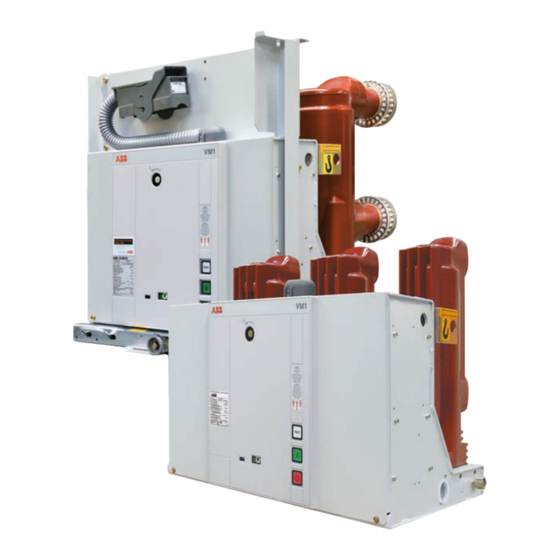
Page 20: Figures
Figures Figure 9/2: Vacuum circuit-breaker, type VM1, for fixed installation, Figure 9/1: Vacuum circuit-breaker, type VM1, for fixed installation, 12 kV, ≤ 1250 A, ≤ 31.5 kA, 12 kV, ≤ 1250 A, ≤ 31.5 kA, mechanism side. pole side. Figure 9/3: Vacuum circuit-breaker, type VM1, high-current, Figure 9/4: Vacuum circuit-breaker, type VM1, high-current, for fixed installation, 12 kV, 1600...2000 A, ≤...
Need help?
Do you have a question about the VM1 and is the answer not in the manual?
Questions and answers