Table of Contents
Advertisement
Advertisement
Table of Contents

Related Manuals for ABB VUCG.N


Summary of Contents for ABB VUCG.N
- Page 1 1ZSC000562-AAX en, Rev. 1 On-load tap-changers, type VUC Technical guide...
- Page 2 Any specific application not covered should be referred directly to ABB, or its authorized representative. ABB makes no warranty or representation and assumes no liability for the accuracy of the information in this document or for the use of such information. All information in this document is subject to change without notice.
- Page 3 Manufacturer’s declaration The manufacturer ABB AB Components SE-771 80 LUDVIKA Sweden Hereby declares that The products On-load tap-changers, type VUC with motor-drive mechanisms, types BUE and BUL comply with the following requirements: By design, the machine, considered as a component of a mineral oil filled power transformer, complies with the requirements of •...
-
Page 4: Table Of Contents
Content Design principles ........................6 On-load tap-changer (OLTC) ................... 6 Diverter switches ......................8 Diverter switch housing and top section ................. 10 Painting .......................... 11 Operating mechanism ..................... 11 Transition resistors ......................11 Special applications, load conditions, and environments ..........11 Insulating liquids...................... - Page 5 Type VUCG.E and VUCG.N with tap selector type C and cover mounting ....34 Type VUCG.E and VUCG.N with tap selector III and with tie-in resistor switch ... 35 Type VUCG.E and VUCG.N with tap selector F and with tie-in resistor switch .... 36 Type VUCG.R and VUCG.B with tap selector F and with tie-in resistor switch ...
-
Page 6: Design Principles
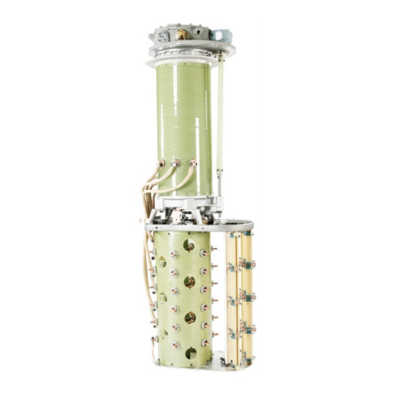
Design principles On-load tap-changer (OLTC) is mounted beneath the diverter switch housing, consists VUC vacuum diverter switch tap-changer family comes in a of the fine tap selector and usually also of a change-over range of models with ratings suitable for the most frequent selector. - Page 7 Buffer springs Cover Bevel gear with position indicator Lifting eyes Connection flanges (x4) Top section Flange for connection to gas operated relay (transformer main tank) Shielding-ring Oil draining tube Insulating shaft Shielding-ring Diverter switch Insulating Transition resistors cylinder Plug-in contacts Main vacuum interrupters Bushings connecting Guide pins...
-
Page 8: Diverter Switches
Diverter switches The vacuum interrupters have a very long life time but yet are The diverter switches with vacuum interrupters are of the mounted for easy replacement when needed, for instance in high-speed, spring-operated type with resistors as transition industrial applications when the number of operations might impedance. - Page 9 Tap selectors The tap selectors available for the VUC range of tap-changers Although the tap selectors for the VUC range of tap-changer are C, III and F. Tap selector C can be combined with VUCG are available in various sizes, all of them have similar functions diverter switches.
-
Page 10: Diverter Switch Housing And Top Section
O-ring gaskets with elastic pressure. Each the transformer’s active part. ready-made unit is tested under vacuum and the outside is exposed to helium and checked for leaks with the use of a helium gas detector. VUCG.N/C VUCG.N/III VUCG.N/F VUCL.N/III VUCL.N/F... -
Page 11: Painting
Special applications, load conditions, and environments The diverter switch housing top sections are finish coated with Please contact ABB for advice in the following cases: a blue-grey color, Munsell 5,5 B 5,5/1,25, corrosion class C3 according to SS-EN ISO 12944-2 and SS-EN ISO 9223. For –... -
Page 12: Tap-Changer Principles Of Operation
Tap-changer principles of operation Switching sequence, VUCG vacuum interrupter then closes, leading to an associated By using an auxiliary contact system (MC, RC) in combination circulating current driven by the difference in voltage potential, with the vacuum interrupters (MVI, RVI) only two vacuum Fig. - Page 13 Fig. 8. Fig. 12. Fig. 9. Fig. 13. Fig. 10. Fig. 14. Fig. 11. Fig. 15. 1ZSC000562-AAX en, Rev. 1 | Technical guide VUC 13...
-
Page 14: Switching Sequence, Vucl
Switching sequence, VUCL transition resistor (TR), Fig. 19. The main contact (MC) is then By using an auxiliary contact system (MC, RC) in combination rotated (Figs. 20 and 21) in order to connect to v. The main with the vacuum interrupters (MVI, RVI) only two vacuum vacuum interrupter then closes, leading to an associated interrupters are required per phase. - Page 15 Fig. 20. Fig. 24. Fig. 21. Fig. 25. Fig. 22. Fig. 26. Fig. 23. Fig. 27. 1ZSC000562-AAX en, Rev. 1 | Technical guide VUC 15...
-
Page 16: Type Of Regulation
Type of regulation Linear switching (type L) The regulating range is equal to the voltage of the tapped winding. No change-over selector is used. Fig. 28. Fig. 28. Change-over selector for plus/minus switching (type R) The change-over selector extends the regulating range to twice the voltage of the tapped winding, by connecting the main winding to different ends of the regulating winding, and thereby reversing the magnetic flux generated by the... -
Page 17: Type Of Connection
Type of connection Three-phase neutral point (N) Only one unit is required for all three phases. The transformers neutral point is in the tap-changer. Fig. 31. Single-phase (E) Only one unit is required Fig. 32. Three-phase delta (B) Two units required. Driven by a common motor-drive. One unit common for two phases. -
Page 18: Tap-Changer Characteristics And Technical Data
Tap-changer characteristics and technical data Type designation VUCG . . XXXX/YYYY/Z . VUCL . . XXXX/YYYY/Z . Example VUCGRE 650/700/C Type of tap-changer VUC... Diverter switch with vacuum interrupters Type of regulation Linear Plus/Minus Coarse/Fine Type of connection Three-phase neutral point (one unit) Single-phase (one unit) Three-phase fully insulated (three units) Three-phase delta (two units;... -
Page 19: Diverter Switches
2) Only available in E, T connection and requires forced current splitting during Enforced current splitting during operation can be used when operation, see that section. Contact ABB for more information. the diverter switch has a lower current rating than the tap... -
Page 20: Rated Phase Step Voltage
The rated phase step voltage is a function of the rated For short versions, there might be restrictions in applications through current as shown in the diagrams below. other than network. 3500 3000 2500 VUCG.N,B,E,T 2000 VUCG.N,B,E,T VUCG.E,T Short version Short version 1500... -
Page 21: Coarse Fine Regulation Leakage Inductance Switching
– Contact temperature rise test The leakage inductance value can be given in the order – Switching tests data sheet or can be calculated by ABB from active part – Short-circuit current test dimensions and number of turns. For more information, –... -
Page 22: Insulation Levels
Insulation levels LI is the lightning impulse (1.2/50 µs), and Pf is the power corresponding frequency test voltage (60 s). The insulation levels are contact in indicated as impulse withstand voltage – power frequency adjacent phase withstand voltage. The tests were carried out according to IEC 60214-1, 2014-05, with a new tap-changer and clean insulation transformer oil LC set -30 °C according to IEC 60296, 2012-02. -
Page 23: Withstand Voltages
Withstand voltages VUCG with tap selector C All values given as 1.2/50 µs impulse withstand voltage (kV) – power frequency withstand voltage (kV). a1 is not valid since the contact locations are such that electrically adjacent contacts are never physically adjacent, see connection diagrams in this document. -
Page 24: Vucg With Tap Selector Iii Shielded Version
VUCG with tap selector III shielded version All values given as 1.2/50 µs impulse withstand voltage (kV) – power frequency withstand voltage (kV). Type of No. of Within one phase Between phases for neutral regulation positions point 300-125 550-180 100-20 100-20 550-180 15-16... -
Page 25: Vucl With Tap Selector Iii Unshielded Version
VUCL with tap selector III unshielded version All values given as 1.2/50 µs impulse withstand voltage (kV) – power frequency withstand voltage (kV). Type of No. of Within one phase Between phases for neutral regulation positions point 300-125 490-150 100-20 100-20 500-160 15-16... -
Page 26: Short-Circuit Current Strength
700, 1000 N,B,E,T 1300 700, 1000, 1300 N,B,E,T Table 12. 1) In case of VUC..E,T higher values are possible on request. 2) For times longer than 3 s, contact ABB for advice. 26 Technical guide VUC | 1ZSC000562-AAX en, Rev. 1... -
Page 27: Highest Phase Service Voltage Across The Regulating Winding
Also dielectric strengths and influence from Rated through-current moisture need to be considered. Please contact ABB for more The rated through-current of the tap-changer is the current information. that the tap-changer is capable of transferring from one... -
Page 28: Coarse/Fine Regulation Leakage Inductance Switching
For the tap-changer but can be mounted under the tap selector more information, see IEC 60214-2, 2004-10, or consult ABB provided that tie-in resistor switch is not used. Please contact for advice. - Page 29 When ordering, give the winding layout and information different tap selectors: according to the example in Fig. 47 and Table 13, and ABB will calculate whether tie-in resistors are needed or not. If needed, ABB will choose the correct tie-in resistors. If a tie-in...
-
Page 30: Installation And Maintenance
For details of oil filling, consult the appropriate Installation and commissioning guide. Maintenance For maintenance, please contact ABB or make sure that personnel performing maintenance are trained and certified by ABB. 30 Technical guide VUC | 1ZSC000562-AAX en, Rev. 1... -
Page 31: Oil Filling
The minimum and maximum lengths refer to mechanical preferably higher in the transformer tank. For higher pressure design only. For L2 vertical shaft, see the dimension drawings differences, contact ABB. on the following pages. Other shaft arrangements are available on request. - Page 32 Fig. A VUCG.N, E VUCL.N, E Fig. B VUCG.B Fig. C VUCL.B Fig. D Fig. E VUCG.T VUCL.T Fig. F Fig. 49. Designation of operating shafts. 32 Technical guide VUC | 1ZSC000562-AAX en, Rev. 1...
-
Page 33: Dimensions
Dimensions, type VUCG The design, technical data and dimensions are subject to alteration without notice. The dimension drawings in this guide show overall dimensions. For detailed information, see the dimension drawings in the website www.abb.com/ electricalcomponents. For tap Impulse withstand... -
Page 34: Type Vucg.e And Vucg.n With Tap Selector Type C And Cover Mounting
C/L Diverter switch Section A – A Plus/Minus and Coarse/Fine switching Section A – A Linear switching Fig. 50. Dimensions, type VUCG.E and VUCG.N with tap selector type C and cover mounting. 34 Technical guide VUC | 1ZSC000562-AAX en, Rev. 1... -
Page 35: Type Vucg.e And Vucg.n With Tap Selector Iii And With Tie-In Resistor Switch
C/L Diverter switch Section A - A Plus/Minus and Coarse/Fine switching Section A - A Linear switching Fig. 51. Dimensions, type VUCG.E and VUCG.N with tap selector III and with tie-in resistor switch. 1ZSC000562-AAX en, Rev. 1 | Technical guide VUC 35... -
Page 36: Type Vucg.e And Vucg.n With Tap Selector F And With Tie-In Resistor Switch
Type VUCG.E with tap selector F and with tie-in resistor switch Fig. 52. Dimensions, type VUCG.E with tap selector F and with tie-in resistor switch. 36 Technical guide VUC | 1ZSC000562-AAX en, Rev. 1... -
Page 37: Type Vucg.r And Vucg.b With Tap Selector F And With Tie-In Resistor Switch
Type VUCG.B with tap selector F and with tie-in resistor switch Design for premounting on the active part of the transformer Fig. 53. Dimensions, type VUCG.B with tap selector F and with tie-in resistor switch. 1ZSC000562-AAX en, Rev. 1 | Technical guide VUC 37... -
Page 38: Dimensions, Type Vucl
The design, technical data and dimensions are subject to alteration without notice. The dimension drawings in this guide show overall dimensions. For detailed information, see the dimension drawings in the website www.abb.com/ electricalcomponents. Impulse withstand voltage to earth (kV) H1 (mm) -
Page 39: Type Vucl.e And Vucl.n With Tap Selector Iii And With Tie-In Resistor Switch
Type VUCL.E and VUCL.N with tap selector III and with tie-in resistor switch Section A – A Plus/Minus and Coarse/Fine switching Section A – A Linear switching Fig. 54. Dimensions, type VUCL.E and VUCL.N with tap selector III and with tie-in resistor switch. 1ZSC000562-AAX en, Rev. -
Page 40: Type Vucl.b With Tap Selector Iii And With Tie-In Resistor Switch
Type VUCL.B with tap selector III and with tie-in resistor switch Design for premounting on the active part of the transformer Fig. 55. Dimensions, type VUCL.B with tap selector III and with tie-in resistor switch. 40 Technical guide VUC | 1ZSC000562-AAX en, Rev. 1... -
Page 41: Type Vucl.e And Vucl.n With Tap Selector F And With Tie-In Resistor Switch
Type VUCL.E and VUCL.N with tap selector F and with tie-in resistor switch Section A – A Plus/Minus and Coarse/Fine switching Fig. 56. Dimensions, type VUCL.E and VUCL.N with tap selector F and with tie-in resistor switch. 1ZSC000562-AAX en, Rev. 1 | Technical guide VUC 41... -
Page 42: Type Vucl.b With Tap Selector F And With Tie-In Resistor Switch
Type VUCL.B with tap selector F and with tie-in resistor switch Design for premounting on the active part of the transformer Fig. 57. Dimensions, type VUCL.B with tap selector F and with tie-in resistor switch. 42 Technical guide VUC | 1ZSC000562-AAX en, Rev. 1... -
Page 43: Motor-Drive Mechanisms
Motor-drive mechanisms 1050 1274 1197 626 475 BUL2 BUE2 Fig. 58. Dimensions, motor-drive mechanisms. 1ZSC000562-AAX en, Rev. 1 | Technical guide VUC 43... -
Page 44: Oil Conservator
70 kPa. For higher manufacturer must provide a conservator for the tap-changer. pressure difference, contact ABB for advice. 6. The oil level for the tap-changer should be equal or below The diverter switch housing needs to be connected to an oil the oil level of the transformer. -
Page 45: Appendices: Single-Phase Diagrams
Appendices: Single-phase diagrams The basic connection diagrams illustrate the different types of The tap-changer can also be connected in such a way that switching and the appropriate connections to the transformer position 1 gives a minimum effective number of turns in the windings. - Page 46 Appendix 1: Single-phase diagrams for VUCG/C Linear Plus/Minus Coarse/Fine 7 steps Number of loops: Number of tap positions: 8 steps Number of loops: 4 + 4 Number of tap positions: 9 steps Number of loops: Number of tap positions: 10 steps Number of loops: 5 + 5 Number of tap positions:...
- Page 47 Appendix 1: Single-phase diagrams for VUCG/C Linear Plus/Minus Coarse/Fine 11 steps Number of loops: Number of tap positions: 12 steps Number of loops: 6 + 6 Number of tap positions: 13 steps Number of loops: Number of tap positions: 14 steps Number of loops: 7 + 7 Number of tap positions:...
- Page 48 Appendix 1: Single-phase diagrams for VUCG/C Linear Plus/Minus Coarse/Fine 15 steps Number of loops: Number of tap positions: 16 steps Number of loops: 8 + 8 Number of tap positions: 17 steps Number of loops: Number of tap positions 18 steps Number of loops: 9 + 10 Number of tap positions:...
- Page 49 Appendix 1: Single-phase diagrams for VUCG/C Linear Plus/Minus Coarse/Fine 20 steps Number of loops: 10 + 10 Number of tap positions: 22 steps Number of loops: 11 + 12 Number of tap positions: 24 steps Number of loops: 12 + 12 Number of tap positions: 26 steps Number of loops:...
- Page 50 Appendix 1: Single-phase diagrams for VUCG/C Linear Plus/Minus Coarse/Fine 28 steps Number of loops: 14 + 14 Number of tap positions: 30 steps Number of loops: 15 + 16 Number of tap positions: 32 steps Number of loops: 16 + 16 Number of tap positions: 34 steps Number of loops:...
-
Page 51: Appendix 2: Single-Phase Diagrams For Vucg/Iii And Vucl/Iii
Appendix 2: Single-phase diagrams for VUCG/III and VUCL/III Linear Plus/Minus Coarse/Fine 4 steps Number of loops: Number of tap positions: 5 steps Number of loops: Number of tap positions: 6 steps Number of loops: Number of tap positions: 7 steps Number of loops: Number of tap positions: 1ZSC000562-AAX en, Rev. - Page 52 Appendix 2: Single-phase diagrams for VUCG/III and VUCL/III Linear Plus/Minus Coarse/Fine 8 steps Number of loops: 4 + 4 Number of tap positions: 9 steps Number of loops: Number of tap positions: 10 steps Number of loops: 5 + 5 Number of tap positions: 11 steps Number of loops:...
- Page 53 Appendix 2: Single-phase diagrams for VUCG/III and VUCL/III Linear Plus/Minus Coarse/Fine 12 steps Number of loops: 6 + 6 Number of tap positions: 13 steps Number of loops: Number of tap positions: 14 steps Number of loops: 7 + 7 Number of tap positions: 15 steps Number of loops:...
- Page 54 Appendix 2: Single-phase diagrams for VUCG/III and VUCL/III Linear Plus/Minus Coarse/Fine 16 steps Number of loops: 8 + 8 Number of tap positions: 17 steps Number of loops: Number of tap positions: 18 steps Number of loops: 9 + 10 Number of tap positions: 19 steps Number of loops:...
- Page 55 Appendix 2: Single-phase diagrams for VUCG/III and VUCL/III Linear Plus/Minus Coarse/Fine 20 steps Number of loops: 10 + 10 Number of tap positions: 21 steps Number of loops: Number of tap positions: 22 steps Number of loops: 11 + 12 Number of tap positions: 24 steps Number of loops:...
- Page 56 Appendix 2: Single-phase diagrams for VUCG/III and VUCL/III Linear Plus/Minus Coarse/Fine 26 steps Number of loops: 13 + 14 Number of tap positions: 28 steps Number of loops: 14 + 14 Number of tap positions: 30 steps Number of loops: 15 + 16 Number of tap positions: 32 steps...
- Page 57 Appendix 2: Single-phase diagrams for VUCG/III and VUCL/III Linear Plus/Minus Coarse/Fine 34 steps Number of loops: 17 + 18 Number of tap positions: 1ZSC000562-AAX en, Rev. 1 | Technical guide VUC 57...
-
Page 58: Appendix 3: Single-Phase Diagrams For Vucg/F And Vucl/F
Appendix 3: Single-phase diagrams for VUCG/F and VUCL/F Linear Plus/Minus Coarse/Fine 4 steps Number of loops: Number of tap positions: 5 steps Number of loops: Number of tap positions: 6 steps Number of loops: Number of tap positions: 7 steps Number of loops: Number of tap positions: 58 Technical guide VUC | 1ZSC000562-AAX en, Rev. - Page 59 Appendix 3: Single-phase diagrams for VUCG/F and VUCL/F Linear Plus/Minus Coarse/Fine 8 steps Number of loops: 4 + 4 Number of tap positions: 9 steps Number of loops: Number of tap positions: 10 steps Number of loops: 5 + 5 Number of tap positions: 11 steps Number of loops:...
- Page 60 Appendix 3: Single-phase diagrams for VUCG/F and VUCL/F Linear Plus/Minus Coarse/Fine 12 steps Number of loops: 6 + 6 Number of tap positions: 13 steps Number of loops: Number of tap positions: 14 steps Number of loops: 7 + 7 Number of tap positions: 15 steps Number of loops:...
- Page 61 Appendix 3: Single-phase diagrams for VUCG/F and VUCL/F Linear Plus/Minus Coarse/Fine 16 steps Number of loops: 8 + 8 Number of tap positions: 17 steps Number of loops: Number of tap positions: 18 steps Number of loops: 9 + 10 Number of tap positions: 20 steps Number of loops:...
- Page 62 Appendix 3: Single-phase diagrams for VUCG/F and VUCL/F Linear Plus/Minus Coarse/Fine 22 steps Number of loops: 11 + 12 Number of tap positions: 24 steps Number of loops: 12 + 12 Number of tap positions: 26 steps Number of loops: 13 + 14 Number of tap positions: 28 steps...
- Page 63 Appendix 3: Single-phase diagrams for VUCG/F and VUCL/F Linear Plus/Minus Coarse/Fine 30 steps Number of loops: 15 + 16 Number of tap positions: 32 steps Number of loops: 16 + 16 Number of tap positions: 34 steps Number of loops: 17 + 18 Number of tap positions: 1ZSC000562-AAX en, Rev.
- Page 64 Contact us ABB AB Components SE-771 80 Ludvika, Sweden Phone: +46 240 78 20 00 Fax: +46 240 121 57 E-Mail: sales@se.abb.com www.abb.com/electricalcomponents...
Need help?
Do you have a question about the VUCG.N and is the answer not in the manual?
Questions and answers