Table of Contents
Advertisement
Quick Links
Advertisement
Table of Contents

Related Manuals for SYMEO LPR-1DHP-291


Summary of Contents for SYMEO LPR-1DHP-291
- Page 1 SYMEO L OCAL OSITIONING ADAR ® Product: LPR -1DHP-291 Product Documentation...
-
Page 2: Table Of Contents
SYMEO Local Positioning Radar System -1DHP-291 – Product Documentation ® Content CONTENT ..........................2 SAFETY NOTES ......................5 ® THE LPR -1DHP-291 ....................8 RADAR BASICS ......................9 Radar Distance Measurement Principle ..............9 Radar Beam and Field of View (FoV) ................ 9 Fresnel Zone ...................... - Page 3 SYMEO Local Positioning Radar System -1DHP-291 – Product Documentation ® General Mounting Instructions ................25 Mounting for Primary Radar Mode ................25 Mounting for Secondary Radar Mode ..............26 Mounting for Diversity Radar Mode ................ 27 QUICK SETUP ......................29 Initial Setup .......................
- Page 4 SYMEO Local Positioning Radar System -1DHP-291 – Product Documentation ® ® The documentation for the LPR -1DHP-291 Local Positioning Radar System is published by: SYMEO GmbH Prof.-Messerschmitt-Str. 3 D-85579 Neubiberg www.symeo.com If you have any questions or suggestions, please contact: Email: info@symeo.com...
-
Page 5: Safety Notes
SYMEO Local Positioning Radar System -1DHP-291 – Product Documentation ® Safety Notes General ® The LPR -1DHP-291 is a radar distance measurement sensor that may be used to measure distances between a radar unit and a reflector or between two radar units. - Page 6 SYMEO Local Positioning Radar System -1DHP-291 – Product Documentation ® Power Supply While installing or using it in open-air, transient overvoltage cannot be excluded. Overvoltage protection is to be used for low voltage in accordance with DIN EN 61643-21 and IEC 61643-21.
- Page 7 SYMEO Local Positioning Radar System -1DHP-291 – Product Documentation ® autorisée aux deux conditions suivantes: (1) l'appareil ne doit pas produire de brouillage, et (2) l'utilisateur de l'appareil doit accepter tout brouillage radioélectrique subi, même si le brouillage est susceptible d'en compromettre le fonctionnement.
-
Page 8: The Lpr ® -1Dhp-291
SYMEO Local Positioning Radar System -1DHP-291 – Product Documentation ® ® The LPR -1DHP-291 ® The LPR -1DHP-291 is a radar distance measurement sensor, which performs 1D distance measurements for short, medium and long ranges with highest accuracy. The radar sensor can be operated in three different radar modes: primary radar mode, secondary radar mode and diversity radar mode. -
Page 9: Radar Basics
SYMEO Local Positioning Radar System -1DHP-291 – Product Documentation ® Radar Basics Radar Distance Measurement Principle ® The LPR -1DHP-291 radar distance sensors use electromagnetic waves to measure the distance and speed between two radars (secondary radar mode) or a single radar and a reflector (primary radar mode). -
Page 10: Fresnel Zone
SYMEO Local Positioning Radar System -1DHP-291 – Product Documentation ® Fresnel Zone The area for radio transmission between two antennas is called Fresnel zone. The main part of energy is concentrated in the first Fresnel zone. The Fresnel zone must be free of any obstacles to ensure that the signal is not attenuated or interrupted. -
Page 11: Secondary Radar Mode
SYMEO Local Positioning Radar System -1DHP-291 – Product Documentation ® Figure 3.3: Primary radar mode measurement setup 3.4.2 Secondary Radar Mode In secondary radar mode, two radars measure the distance and speed between each other. ® Figure 3.4 shows the typical setup of two LPR -1DHP-291 radars for a secondary radar range measurement. -
Page 12: Diversity Radar Mode
SYMEO Local Positioning Radar System -1DHP-291 – Product Documentation ® Figure 3.4: Secondary radar mode measurement setup 3.4.3 Diversity Radar Mode In diversity radar mode, four radar units are grouped into two pairs, which are mounted in a way that two secondary radar measurements are performed side by side separated by a defined distance. -
Page 13: Bandwidth Modes
SYMEO Local Positioning Radar System -1DHP-291 – Product Documentation ® Bandwidth Modes ® The LPR -1DHP-291 operates in the 57 - 64 GHz band. Depending on your used region and regulatory authority setting, a limited number of bandwidth modes are available for selection in the WebUI. -
Page 14: Range
SYMEO Local Positioning Radar System -1DHP-291 – Product Documentation ® Range ® To maximize the range of an LPR -1DHP-291 measurement setup the following aspects must be taken into account: Mounting position Adhere to the mounting instructions (see chapter 5). Ensure minimum alignment error... -
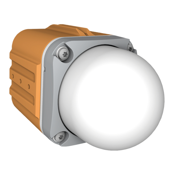
Page 15: Components
SYMEO Local Positioning Radar System -1DHP-291 – Product Documentation ® Components Device Overview ® The LPR -1DHP-291 consists of the following parts (see Figure 4.1 and Figure 4.2): Dielectric lens (A1) focuses the radar beam Metal gland (A2) - Page 16 SYMEO Local Positioning Radar System -1DHP-291 – Product Documentation ® ® Figure 4.1: Front view of the LPR -1DHP-291 Components Copyright © Symeo GmbH 2022 Page 16 of 37 DOC.EDO.000519.0001.EN_LPR-1DHP-291_Product-Documentation.docx...
- Page 17 SYMEO Local Positioning Radar System -1DHP-291 – Product Documentation ® ® Figure 4.2: Side view of the LPR -1DHP-291 Components Copyright © Symeo GmbH 2022 Page 17 of 37 DOC.EDO.000519.0001.EN_LPR-1DHP-291_Product-Documentation.docx...
-
Page 18: Led Display
SYMEO Local Positioning Radar System -1DHP-291 – Product Documentation ® ® Figure 4.3: LPR -1DHP-291 housing dimensions LED Display The LEDs (Status LED on the left and Ethernet LED on the right) indicate the different states of the device (see Table 4.1). -
Page 19: Connectors
Ethernet connector (C2) for network connection The necessary connectors for manufacturing cables that fit your installation and cable length are available from Symeo and are described in the following chapters. We recommend the following tool set from PHOENIX CONTACT for proper M12 torque moment screwing: •... -
Page 20: Ethernet M12 (Tcp/Ip Or Profinet)
SYMEO Local Positioning Radar System -1DHP-291 – Product Documentation ® Pin Assignment Power Supply 11 V DC – 36 V DC M12 Connector Pin 1 Pin 2 (bridged to Pin 1) Pin 3 Pin 4 (bridged to Pin 3) Table 4.2: Pin assignment power supply 4.3.2... - Page 21 If the Ethernet connecter is left unused, install the protective cap of the connector. Connector Cable M12 – RJ45 A connector cable M12 – RJ45 (2m) for connecting the radar to a PC for initial commissioning and configuration is available from Symeo: • Symeo order number: MTE102007 Components Copyright ©...
-
Page 22: Mounting Brackets
Mounting Bracket – MTM102513 4.4.1 ® For mounting the LPR -1DHP-291 to a pipe, a mounting bracket is available from Symeo. The pipe diameter should measure between 40 and 75 mm. ® Figure 4.6: LPR -1DHP-291 mounted to a pipe with the mounting bracket Figure 4.7: MTM102513 dimensions... -
Page 23: Diversity Mounting Bracket - Mtm102467
“Symeo_Docs”. Protective cover – MTM102512 4.4.3 In addition to mounting brackets MTM102513 and Diversity mounting bracket MTM102647, protective covers (Symeo part number MTM102512) are available for use in snowy or extreme dusty environments. Figure 4.9: MTM102512 Cover Components Copyright © Symeo GmbH 2022 Page 23 of 37 DOC.EDO.000519.0001.EN_LPR-1DHP-291_Product-Documentation.docx... -
Page 24: Corner Reflectors
Figure 4.11: Corner reflector 250 mm Adjustable mounting device tube/wall – MTM000169 4.5.3 For mounting the corner reflector, a pipe mounting bracket is available from Symeo. The pipe diameter should be between 40 and 75 mm. Components Copyright © Symeo GmbH 2022 Page 24 of 37 DOC.EDO.000519.0001.EN_LPR-1DHP-291_Product-Documentation.docx... -
Page 25: Mounting
SYMEO Local Positioning Radar System -1DHP-291 – Product Documentation ® Mounting General Mounting Instructions Site-specific mounting instructions must be followed if available. The more accurately the radar units and reflectors are aligned to each other, the better the performance of the measurement setup will be in terms of accuracy and range. -
Page 26: Mounting For Secondary Radar Mode
SYMEO Local Positioning Radar System -1DHP-291 – Product Documentation ® Radar and radar reflector must be aligned to each other with maximum accuracy (at least +/- 2,5°). Minimum horizontal and vertical offset between radar and reflector must be ensured. -
Page 27: Mounting For Diversity Radar Mode
SYMEO Local Positioning Radar System -1DHP-291 – Product Documentation ® Connect the power supply and Ethernet cable with the M12 connectors as specified in chapter 4.3.1 and 4.3.2 to both stations. The Ethernet connection at the Slave unit is only required for configuration and can be removed during operation. - Page 28 SYMEO Local Positioning Radar System -1DHP-291 – Product Documentation ® Figure 5.2: Mounting positions for mounting in the diversity mount for the master and slave side Mounting Copyright © Symeo GmbH 2022 Page 28 of 37 DOC.EDO.000519.0001.EN_LPR-1DHP-291_Product-Documentation.docx...
-
Page 29: Quick Setup
Connect the radar units to a PC via Ethernet and open the Webinterface (WebUI) in a Webbrowser (http://192.168.1.99). Sign in to the WebUI. Enter the user name “Symeo” and the password “xxxxx” and press “Login”. Now your status is displayed as “Logged in”. -
Page 30: Quick Setup For Secondary Radar Mode
SYMEO Local Positioning Radar System -1DHP-291 – Product Documentation ® Quick Setup for Secondary Radar Mode The following settings must be set in the WebUI of the master and slave sensor for operation in secondary radar mode. Only the Master unit outputs range data. - Page 31 SYMEO Local Positioning Radar System -1DHP-291 – Product Documentation ® Master 1 Device -> Settings -> Measurement Station mode = Master Bandwidth mode = Choose a bandwidth that fits your required range and accuracy Channel block = Use recommended selection ®...
- Page 32 SYMEO Local Positioning Radar System -1DHP-291 – Product Documentation ® Master 1 Device -> Settings -> Measurement details Diversity mode = Enabled Diversity partner IP address = IP address of Master 2 Diversity partner sync channel = Sync channel of Master 2 Master 2 ...
-
Page 33: The Customer Protocol
SYMEO Local Positioning Radar System -1DHP-291 – Product Documentation ® The Customer Protocol ® The customer protocol (Binary Protocol XP) is the standard data protocol between LPR 1DHP-291 and users for exchanging measurement and relay data with the help of different data types in binary data format. -
Page 34: Data Types
SYMEO Local Positioning Radar System -1DHP-291 – Product Documentation ® Data Types Type 0x16 – Distance Data 7.2.1 -1DHP-291 → User ® Direction: LPR The data type 0x16 is the standard output data type. It contains measurement data, system status information and settings. The default protocol frame length is 47 bytes. - Page 35 SYMEO Local Positioning Radar System -1DHP-291 – Product Documentation ® Diversity Status: The last bit refers to the current station The second last bit refers to the partner station 0: indicates errorless operation 1: indicates and error at the corresponding station or that the station is not visible via...
- Page 36 SYMEO Local Positioning Radar System -1DHP-291 – Product Documentation ® Distance Error Codes The following errors are indicated in the error field in the distance data type: Value Content Description (hex) 0x00 No error Measurement valid 0x01 No peak detected...
-
Page 37: Technical Data
SYMEO Local Positioning Radar System -1DHP-291 – Product Documentation ® Technical Data Feature Value Radar measuring mode Primary, secondary, diversity radar 57,0 – 64,0 GHz Frequency range Supply voltage 11 - 36 V Power consumption Ambient temperature -40 °C to +75°C...
Need help?
Do you have a question about the LPR-1DHP-291 and is the answer not in the manual?
Questions and answers