Table of Contents

Related Manuals for Despatch MIC 1422


Summary of Contents for Despatch MIC 1422
- Page 1 MIC 1422 MIC 1422 MIC 1422 MIC 1422 E-90 MICROBASED CONTROLLER MICROBASED CONTROLLER MICROBASED CONTROLLER MICROBASED CONTROLLER PN 136108 REVISION 10-07 INSTRUCTION MANUAL INSTRUCTION MANUAL INSTRUCTION MANUAL INSTRUCTION MANUAL...
-
Page 3: Table Of Contents
TABLE OF CONTENTS TABLE OF CONTENTS ....................iii SECTION 1: PRODUCT DESCRIPTION ............... 1 1.1 General ........................1 1.2 Displays......................... 2 1.3 Control........................2 1.4 Alarms ........................2 1.5 Process Variable/Setpoint Value Re-Transmission Output........3 SECTION 2: INSTALLATION AND WIRING..............5 2.1 Mounting ....................... - Page 4 SECTION 7: TEST MODE ................... 43 7.1 Test Mode Description ..................43 SECTION 8: CONFIGURATION MODE ..............45 8.1 Configuration Mode Description ................45 8.2 Hardware Definition Code ................... 48 SECTION 9: CALIBRATION MODE................51 9.1 Entering Calibration Mode................... 51 9.2 Calibrating The Universal Input ................
-
Page 5: Section 1: Product Description
SECTION 1: PRODUCT DESCRIPTION 1.1 General This instrument is a microprocessor based single loop controller capable of measuring, displaying and controlling temperature, pressure, flow, and level from a variety of inputs. Most outputs are easily tuned using the instrument Pre-Tune and Auto-Tune, or RaPID (Response assisted PID) functions. -
Page 6: Displays
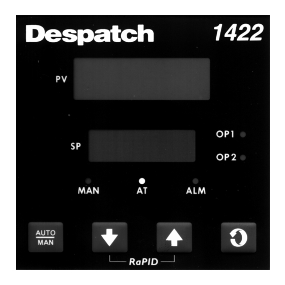
1.2 Displays Each instrument is provided with dual displays and status indicators as shown in Figure 1 -1. The upper display (RED) displays the value of the process variable. The lower display (GREEN) displays the setpoint value. 1.3 Control The instrument can be programmed for on-off, time proportioning, or current proportioning control implementations depending on the model number. -
Page 7: Process Variable/Setpoint Value Re-Transmission Output
FIGURE 1-1 Keys and Indicators 1.5 Process Variable/Setpoint Value Re-Transmission Output If the instrument is specified with this option, this output may be scaled over any desired range and re-transmitted. -
Page 9: Section 2: Installation And Wiring
SECTION 2: INSTALLATION AND WIRING 2.1 Mounting Electrical code requirements and safety standards should be observed and installation performed by qualified personnel. The electronic components of the instrument may be removed from the housing during installation. To remove the components, grip the side edges of the front panel and pull the instrument forward. - Page 10 FIGURE 2-2 Main Dimensions MIC1422 FIGURE 2-3 Panel Mounting the Controller...
-
Page 11: Wiring Guidelines
2.2 Wiring Guidelines Electrical noise is a phenomenon typical of industrial environments. The following are guidelines that must be followed to minimize the effect of noise upon any instrumentation. Installation Considerations Listed below are some of the common sources of electrical noise in the industrial environment: •... -
Page 12: Ac Power Wiring
AC Power Wiring Neutral (For 115 VAC) It is good practice to assure that the AC neutral is at or near ground potential. To verify this, a voltmeter check between neutral and ground should be done. On the AC range, the reading should not be more than 50 millivolts. -
Page 13: Noise Suppression At The Source
Noise Suppression At The Source Usually when good wiring practices are followed no further noise protection is necessary. Sometimes in severe electrical environments, the amount of noise is so great that it has to be suppressed at the source. Many manufacturers of relays, contactors, etc. -
Page 14: Sensor Placement (Thermocouple Or Rtd)
FIGURE 2-5 2.3 Sensor Placement (Thermocouple or RTD) Two-wire RTDs should be used only with lead lengths less than 10 feet. If the temperature probe is to be subjected to corrosive or abrasive conditions, it should be protected by the appropriate thermowell. The probe should be positioned to reflect true process temperature: •... - Page 15 FIGURE 2-6 Wiring Label...
-
Page 16: Input Connections
2.4 Input Connections In general, all wiring connections are made to the instrument after it is installed. Avoid Electrical Shock. AC power wiring must not be connected to the source distribution panel until all wiring connection procedures are completed. Caution: This equipment is designed for installation in an enclosure which provide adequate protection against electric shock. - Page 17 FIGURE 2-7A 24V Nominal AC/DC Supply The supply connection for the 24V AC/DC option of the instrument are as shown below. Power should be connected via a two pole isolating switch and a 315 mA slow-blow (anti-surge type T) fuse. With the 24V AC/DC supply option fitted, these terminals will accept the following supply voltage ranges: 24V (nominal) AC 50/60 Hz - 20 - 50 V...
- Page 18 FIGURE 2-9 RTD Input Make RTD connections as illustrated below. For a three wire RTD, connect the resistive leg of RTD to terminal 1 and the common legs to terminals 2 and 3. For a two wire RTD, connect one leg to terminal 2 and the other leg to terminal 3 as shown below. A jumper wire supplied by the customer must be installed between terminals 2 and 3.
- Page 19 FIGURE 2-11 Remote Digital Communications - RS485 Make digital communication connections as illustrated below. FIGURE 2-12 Remote Setpoint Input - V/mA/mV and Potentiometer Connections are illustrated below. Terminal 6 is positive and terminal 7 is negative. The remote setpoint input can be configured for linear DC mv, linear DC mA, linear DC Volt or potentiometer.
- Page 20 FIGURE 2-13 Remote Setpoint Selection Connections are made as shown. FIGURE2-14 Dual Setpoint Selection Connections are made as shown.
-
Page 21: Output Connections
2.5 Output Connections FIGURE 2-15 Relay Output 1 (Control Output 1) Connections are made to Output 1 relay as illustrated below. The contacts are rated at 2 amp resistive, 120/240 VAC. FIGURE 2-16 SSR Driver Output 1 (Control Output 1) Connections are made to Output 1 SSR Driver as illustrated below. - Page 22 FIGURE 2-18 Relay Output 2 (Control Output 2 OR Alarm 2) Connections are made to Output 2 relay as illustrated below. The contacts are rated at 2 amp resistive, 120/240 VAC. FIGURE 2-19 SSR Driver Output 2 (Control Output 2 OR Alarm 2) Connections are made to Output 2 SSR Driver as illustrated below.
- Page 23 FIGURE 2-21 Relay Output 3 (Alarm 1) Connections are made to Output 3 relay as illustrated below. The contacts are rated at 2 amp resistive, 120/240 VAC. FIGURE 2-22 SSR Driver Output 3 (Alarm 1) Connections are made to Output 3 SSR Driver as illustrated below. The solid state relay driver is a non-isolated 0-4 VDC nominal signal.
-
Page 25: Section 3: Operation
SECTION 3: OPERATION 3.1 Control Capability The capabilities available in a specific unit are dependent upon the hardware options specified when the instrument is ordered. Refer to Appendix E for the decoding of the instrument model number. Current proportioning control cannot be implemented if a current output was not ordered. -
Page 26: Direct/Reverse Operation Of Outputs
3.3 Direct/Reverse Operation of Outputs Direct operation is typically used with cooling applications. On-Off direct output(s) will turn on when the process variable exceeds setpoint. Proportional direct output(s) will increase the percentage of output as the process value increases within the proportional band. -
Page 27: Current Proportioning Control
When the unit is operating in the Control Mode, the control algorithm determines the output % required to correct for any difference between the process value and the setpoint. The output calculation is affected by Tune Mode parameter adjustments. See Figure 3-1 for proportional bandwidth effect on the output. - Page 28 FIGURE 3-1 Proportional Band 1...
-
Page 29: Power Up Procedure
3.7 Power Up Procedure Verify all electrical connections have been properly made before applying power to the instrument. If the instrument is being powered for the first time, it may be desirable to disconnect the controller output connections. The instrument will be into control following the power up sequence and the output(s) may turn ON. -
Page 30: Front Panel Indicators
UP KEY • Increase the displayed parameter value. • Increase setpoint. DOWN KEY • Decrease the displayed parameter value. • Decrease setpoint. • plus to view the current Hardware Definition Code setting. 3.9 Front Panel Indicators OP1 Indicates the state of the Output 1 relay or SSR driver. When the indicator is ON the relay is energized or the SSR driver is ON. -
Page 31: Section 4: Control Mode
SECTION 4: CONTROL MODE 4.1 Operation After the instrument has performed its power up self test, the Control Mode is active with the setpoint in the lower display and the process variable in the upper display. To view the various parameters in the Control Mode, press the SCROLL key. The lower display shows the parameter name and the upper display shows the current setting of the parameter. -
Page 32: Override Feature
4.3 Override Feature While the instrument is being used with either Dual Setpoint operation or Remote Setpoint operation, the Override feature is available. This enables the active setpoint selected by the digital input to be manually overridden from the keypad. To engage the Override feature, with the instrument displaying the desired setpoint, press the UP and DOWN keys simultaneously. -
Page 33: Manual Control (Percent Output)
If a break is detected in the sensor circuit, the upper display will show: 4.6 Manual Control (Percent Output) Manual Control is not applicable if the Auto/Manual selection in Enable Mode is disabled. If enabled, the Manual Mode may be entered by pressing the AUTO/MANUAL key. The Manual Mode status LED will begin to flash indicating that the Manual Mode is in use. -
Page 34: Setup Modes
4.7 Setup Modes The Setup Modes contain parameters which configure the instrument and affect how the control functions. To access the Setup Modes from the Control Mode, press the SCROLL key until the lower display reads Mod. Press the DOWN key, then press the SCROLL key to view the different modes available. -
Page 35: Section 5: Tune Mode
SECTION 5: TUNE MODE 5.1 Tune Mode Description The Tune Mode contains parameters concerning tuning of the instrument. To access the Tune Mode from the Control Mode, press the SCROLL key until Mod is displayed. Press the DOWN key. This puts the control in Setup Mode. Press the SCROLL key until tunE is displayed. -
Page 36: Manual Tuning Method
5.2 Manual Tuning Method 1. Cycle Time - Time Proportioning Outputs Adjusting the cycle time affects instrument operation Shorter Cycle Time More accurate control Shorter life span of electromechanical components Proportional Bandwidth Proportional Bandwidth is the inverse of gain. Increased Bandwidth = Decreased Gain Increase the Proportional Bandwidth if: The process overshoots excessively... - Page 37 Table 5-1 Tune Mode Parameters STEP DESCRIPTION DISPLAY AVAILABLE SETTINGS FACTORY CODE SETTING Local Setpoint +/- Setpoint Limits Input range minimum Remote +/- Setpoint Limits Read Only Setpoint Setpoint 1 Value +/- Setpoint Limits Read Only Setpoint 2 Value +/- Setpoint Limits Read Only Input Correct iCor...
- Page 38 FIGURE 5-1 Proportional Band & Deadband/Overlap...
-
Page 39: Section 6: Alarm Mode
SECTION 6: ALARM MODE 6.1 Alarm Mode Description The Alarm Mode contains parameters concerning process alarms. To access the Alarm Mode from the Control Mode, press the SCROLL key until Mod is displayed. Press the DOWN key. This puts the control in Setup Mode. Press the SCROLL key until ALA is displayed. - Page 40 Table 6-1 Alarm Mode Parameters STEP DESCRIPTION DISPLAY CODE AVAILABLE SETTINGS FACTORY SETTING Alarm 1 Type ALA1 P-hi=Proc High P_hi nonE=No Alarm bAnd=Band dE=Deviation P-Lo=Proc Low Alarm 2 Type ALA2 Same selection as ALA1 P_hi Alarm Inhibit Inhi nonE=No Inhibit nonE ALA1=Alarm1 Inhibited ALA2=Alarm2 Inhibited...
- Page 41 FIGURE 6-1 Alarm Actuation...
- Page 43 FIGURE 6-2 Alarm Hysteresis...
-
Page 44: Loop Alarm Enable
6.2 Loop Alarm Enable This parameter is the means by which the user can enable or disable the Loop Alarm. The Loop Alarm is a special alarm which detects faults in the control feedback loop by continuously monitoring process variable response to the control output(s). The Loop Alarm, when enabled, repeatedly checks the control output(s) for being at the maximum or minimum limit. -
Page 45: Logical Combination Of Alarms
6.4 Logical Combination of Alarms Two alarms may be combined logically to create an AND/OR situation. They may be configured for Reverse-acting or Direct-acting. Either Output 2 or Output 3 may be assigned as Logical Outputs. Example: Logical OR of Alarm 1 with Alarm 2 Direct-Acting Reverse-Acting AL1 OFF, AL2 OFF: Relay OFF... - Page 46 FIGURE 6-3 Asymmetrical Band Alarm...
-
Page 47: Section 7: Test Mode
SECTION 7: TEST MODE 7.1 Test Mode Description The Test Mode allows manual control of the instrument outputs in order to test their operation. To access the Test Mode from the Control Mode, press the SCROLL key until Mod is displayed. -
Page 49: Section 8: Configuration Mode
SECTION 8: CONFIGURATION MODE 8.1 Configuration Mode Description The Configuration Mode contains parameters concerning output functions of the instrument. To access the Configuration Mode from the Control Mode, press the SCROLL key until Mod is displayed. Press the DOWN key. This puts the control in Setup Mode. Press the SCROLL key until ConF is displayed. - Page 50 STEP DESCRIPTION DISPLAY AVAILABLE SETTINGS FACTORY CODE SETTING Output 2 Usage USE2 Out2=Control (opposite of Out1 Out2 action) Hy_r=Alm Hyst Rev Act** Hy_d=Alm Hyst Dir Act*** LP-r=Loop Reverse LP-d=Loop Direct Ad-r=Rev Logic AND Ad-d=Dir Logic AND Or-r=Rev Logic OR Or-d=Dir Logic OR A2_r=Alm 2 Rev A2_d=Alm2 Dir Output 3 Usage...
- Page 51 The Hardware Definition Code and input jumper configuration may need to be changed. See Appendices A and B. If Remote Setpoint Input has been selected in the Hardware Definition Code, this parameter will appear in the normal Program Mode parameter sequence. The upper display shows a product code which defines the input range.
-
Page 52: Hardware Definition Code
8.2 Hardware Definition Code The Hardware Definition Code is used to represent the hardware installed (input type, Output 1 type, Output 2 type and Output 3 type); this must be compatible with the hardware actually installed. It can be accessed, with the instrument in Configuration Mode (with a prompt inPS, etc. - Page 53 The displayed code may be incremented/decremented using the UP/ DOWN keys as required. The maximum setting available is 4777. For example, the code for a thermocouple input, DC 4-20 mA Output 1 and relay Output 3 would be 2701. When the code is first altered, the code display will flash, until the desired value is displayed and confirmed by pressing the Auto/Manual key.
- Page 54 NOTE: It is essential that this code is changed whenever there is a change to the instrument's hardware configuration (change of input/output type, alarm/ retransmit output added/removed etc.). The instrument's software depends upon this code to ensure that the instrument operates correctly. To exit from the Hardware Definition Code display, depress the DOWN and SCROLL keys simultaneously.
-
Page 55: Section 9: Calibration Mode
SECTION 9: CALIBRATION MODE 9.1 Entering Calibration Mode To enter the Calibration Mode from Setup Mode: Press the SCROLL key until CAL appears in the message display Press the DOWN key to enter the Calibration Mode. NOTE: Calibration should be attempted only on Controllers on which calibration errors have been encountered (see CALIBRATION CHECK). - Page 56 Enter Calibration Mode (Section 9.1). The upper display will then show Input Type Number, in the form: iP_I and the lower display will show: Using the UP/DOWN keys, change the input type number as required (see Table 9-1). NOTE: If required, only one input type may be calibrated. Exception: If it is required to calibrate the thermocouple input (Input Type 5), it is necessary first to calibrate the DC 0 - 50 mV input (Input Type 1).
-
Page 57: Calibrating The Secondary Analog Input
9.3 Calibrating The Secondary Analog Input Equipment Required DC linear input source (0 - 5 V and 0 - 20 mA) with an accuracy better than +/- 0.05% of reading. Case assembly, wired for appropriate input supply (90 - 264V AC 50/60 Hz, 20 - 50 VAC 50/60 HZ or 22-65 VDC). -
Page 58: Exit From Calibration Mode
6. To calibrate all inputs, repeat Steps 1 to 4 for each of the other input types (see Table 9-2) until all three secondary analog input types have been successfully calibrated. Table 9-2 Secondary Analog Input Type Selection Input Type No. Input Type Calibration Input Link Jumper 10... -
Page 59: Section 10: Enable Mode
SECTION 10: ENABLE MODE 10.1 Enable Mode Description The Enable Mode controls access to the various modes available. To access the Enable Mode from the Control Mode, press the SCROLL key until Mod is displayed. Press the DOWN key. This puts the control in Setup Mode. Press the SCROLL key until EnAb is displayed. - Page 60 Table 10-1 Enable Mode Parameters STEP DESCRIPTION DISPLAY AVAILABLE FACTORY CODE SETTINGS SETTING Enable Setpoint Change EnAb = Enable EnAb diS = Disable *Enable Pre Tune EPre EnAb = Enable EnAb diS = Disable Enable Auto Tune EAut EnAb = Enable diS = Disable Enable RaPID Tune ErAP...
-
Page 61: Section 11: Pre-Tune Mode
SECTION 11: PRE-TUNE MODE 11.1 Pre-Tune Mode Description The Pre-Tune Mode may be used to set the instrument's PID parameters to values which are approximately correct, in order to provide a base from which the Auto Tune Mode may optimize tuning. To engage the Pre-Tune Mode, with the instrument in Control Mode, press the SCROLL key until Mod is displayed. -
Page 63: Section 12: Autotune Mode
SECTION 12: AUTOTUNE MODE 12.1 AutoTune Mode and Description The Auto-Tune Mode is used to optimize tuning while the instrument is operating. To access the Auto-Tune Mode, with the instrument in Control Mode, enter the Setup Mode. Press the SCROLL key until Auto is displayed. To engage Auto-Tune, press the UP key. - Page 64 New instruments supplied by the factory contain PID terms set at "DEFAULT" values which have been found to give adequate and safe control over a wide range of applications. In the "Pre-Tune" mode of operation, the "default" PID terms are loaded and the controller demands 100% power until the process value has moved approximately halfway to the setpoint.
-
Page 65: Section 13: Rapid Feature
SECTION 13: RaPID FEATURE 13.1 RaPID Description The RaPID (Response assisted PID) range of controllers have been designed with a unique "fuzzy" logic algorithm which dramatically reduces overshoot and improves settling times on start-up, setpoint changes and disturbances by 70%, without complicating set-up and usage. -
Page 67: Appendix A: Board Layout - Jumper Positioning
APPENDIX A: BOARD LAYOUT - JUMPER POSITIONING FIGURE A-1 OUTPUT 2, OUTPUT 3 REMOVAL... - Page 68 FIGURE A-2 CPU PWA...
- Page 69 FIGURE A-3 PSU PWA WITH RELAY OR SSR OUTPUT 1...
- Page 70 FIGURE A-4 PSU PWA WITH DC OUTPUT 1...
- Page 71 FIGURE A-5 OPTION PWA DC OUTPUT 2/OUTPUT 3...
- Page 72 FIGURE A-6 JUMPER PLACEMENT FOR REMOTE INPUT TYPE...
-
Page 73: Appendix B: Range Codes
APPENDIX B: RANGE CODES The input ranges available (selectable via the front panel) are: For Thermocouple Inputs TYPE INPUT RANGE DISPLAYED TYPE INPUT DISPLAYED CODE RANGE CODE 0 - 1650° C 1127 -328 -1399° F 6727 32 - 3002° F 1128 -200 - 1373°... -
Page 74: For Dc Inputs
For DC Inputs Note: Input conditioning jumper LJ1, LJ2. or LJ3 needs to be changed, see Appendix A. INPUT RANGE DISPLAYED CODE 0-20mA 3413 4-20mA 3414 0-50mV 4443 10-50Mv 4499 0-100 mV 4412 0-5V 4445 1-5V 4434 0-10V 4446 2-10V 4450 Remote Setpoint Input Ranges SECOND INPUT... -
Page 75: Appendix C: Rapid Control Feature
APPENDIX C: RaPID CONTROL FEATURE The RaPID (Response - assisted PID) feature offers dramatic improvements in control quality compared with conventional PID techniques. It responds much more effectively than PID techniques to load conditions. With this feature, the instrument's response at start-up, during setpoint changes and during disturbances shows considerably reduced overshoot and much more shorter settling times (see below). - Page 76 In conditions of frequent change in load characteristics, it is recommended that the Auto-Tune facility is used. Note: With Auto-Tune and RaPID engaged together, Auto-Tune is suspended until RaPID is disengaged, whereupon Auto-Tune will operate automatically. The responses to RaPID being engaged are: Pre-Tune Auto-Tune Response...
-
Page 77: Appendix D: Specifications
APPENDIX D: SPECIFICATIONS Input Specifications General Input Sample Rate: Four per second Input Resolution: 14 bits approximately Input Impedance: Greater than 100M ohm resistive (except for DC mA and V inputs) Isolation: Universal input isolated from all outputs except SSR at 240 VAC Thermocouple Inputs Thermocouple Types: R, S, J, T, K, L, B and N... - Page 78 Dual Setpoint Selection Input Type: Voltage free or TTL compatible Voltage Free Operations: Connections to contacts of external switch or relay; contacts open equal Setpoint 1 selected (minimum contact resistance = 5K ohms), contacts closed equal setpoint 2 selected (maximum contact resistance = 50 ohms) TTL Levels: To select Setpoint 1: -0.6V to 0.8V To select Setpoint 2: 2.0V to 24V...
-
Page 79: Output Specifications
To Select Remote Setpoint/ Setpoint 1: Minimum contact resistance (open): 5K ohms Minimum voltage for (TTL) for " 1 ": 2.0 V Maximum voltage for "1”: 24.0 V Maximum input delay (OFF-ON): 0.5 seconds Minimum input delay (ON-OFF): 0.5 seconds Isolation: 240 VAC isolation from all setpoints and inputs except Remote Setpoint... - Page 80 Output 2 General Types Available: Relay, SSR and DC Relay Contact Type: Single pole double throw (SPDT) Rating: 2A resistive at 120/240V AC Lifetime: > 500,000 operations at rated voltage/current Isolation: Inherent SSR Driver/TTL Drive Capability: SSRD>4.3V DC into 250 ohm minimum Isolation: Not isolated from input or other SSR outputs Resolution:...
-
Page 81: Control Specifications
Resolution: Eight bits in 250 mS (10 bits in 1 second typical, >10 bits in >1 second typical). Update Rate: Four times per second Ranges: 0-20 mA, 4-20 mA, 0-10 V, and 0-5 V NOTE: Changes between V and mA ranges also require jumper movement. Load Impedance: 0 - 20 mA: 500 ohm maximum... -
Page 82: Performance
Alarms Maximum Number: Two "soft" alarms plus Loop Alarm* Maximum # Outputs: Up to 2 outputs can be used for alarm purposes Combination Alarms: Logical OR or AND of alarms to an individual hardware output is available. Hysteresis: 1 LSD to 10% of span Loop Alarm: Detects faults in the control feedback loop by continuously monitoring process variable response to the control output(s) -
Page 83: Dc Outputs
DC Outputs Output 1 Accuracy: 0 - 20mA ± 0.5% of span (20 mA) @250 ohm 4 - 20mA ± 0.5% of span (16 mA) @ 250 ohm 0 - 10V ± 0.5% of span (10 V) @ 2K ohm 0 - 5V ±... -
Page 84: Performance Under Operating Conditions
Performance Under Operating Conditions Temperature Stability: 0.01 % of span /degree C change in ambient temperature Cold Junction Compensation (thermocouple only): Better than ± 1º C Note: Thermocouple must not be grounded! Damage to the cold junction in the control will result! Supply Voltage Influence: Negligible... -
Page 85: Appendix E: Software Reference Sheet
APPENDIX E: SOFTWARE REFERENCE SHEET Tune Parameter Setting iCor ArSt rAtE rSEt HyS1 HyS2 SPrd SPrr rSPo... - Page 86 Alarm Parameter Setting ALA1 ALA2 Inhi (Alm 1 Value) AHy1 (Alm 2 Value) AHy2 LAEn LAti Enable Parameter Setting EPrE EAut ErAP EPtn Etun EALA Etst ECon ECAL ESby ESPr Code...
- Page 87 Configuration Parameter Setting InPS FiLt rinP CtL1 USE2 USE3 CPAr dPoS SPuL SPLL rSPu rSPL o1PL Hardware Definition Setting dEFn OPtn 2inp...
-
Page 88: Appendix F: Flow Chart Of Operation
APPENDIX F: FLOW CHART OF OPERATION... -
Page 89: Appendix G: Model Number Matrix
APPENDIX G: MODEL NUMBER MATRIX...
Need help?
Do you have a question about the MIC 1422 and is the answer not in the manual?
Questions and answers