
Related Manuals for Hitachi VTFX340EUK


Summary of Contents for Hitachi VTFX340EUK
- Page 1 No. 5302 VTFX340EUK VTMX310EUK SERVICE MANUAL SPECIFICATIONS AND PARTS ARE SUBJECT TO CHANGE FOR IMPROVEMENT VIDEO CASSETTE RECORDER May 2003 Digital Media Division...
-
Page 2: Table Of Contents
CONTENTS 1 CAUTIONS FOR SAFETY IN PERFORMING 6 EXPLODEDS VIEWS AND PARTS LIST ..6-1 REPAIR ....... .1-1 6-1 EXPLODED VIEWS . -
Page 3: Cautions For Safety In Performing
CAUTIONS FOR SAFETY IN PERFORMING REPAIR 1-1 IMPORTANT SAFETY PRECAUTIONS 1-1-1 Product Safety Notice H. When a power cord has been replaced, check that 5 - 6 kg of force in any direction will not loosen it. Some electrical and mechanical parts have special I. -
Page 4: Safety Check After Servicing
1-1-3 Safety Check after Servicing Examine the area surrounding the repaired location for damage or deterioration. Observe that screws, parts, Chassis or Secondary Conductor and wires have been returned to their original posi- tions. Afterwards, do the following tests and confirm the specified values to verify compliance with safety Primary Circuit Terminals standards. -
Page 5: Standard Notes For Servicing
1-2 STANDARD NOTES FOR SERVICING 1-2-1 Circuit Board Indications 1-2-3 How to Remove / Install Flat Pack-IC 1. The output pin of the 3 pin Regulator ICs is indi- cated as shown. 1. Removal With Hot-Air Flat Pack-IC Desoldering Machine:. Top View Bottom View (1) Prepare the hot-air flat pack-IC desoldering... - Page 6 With Soldering Iron: (4) Bottom of the flat pack-IC is fixed with glue to the CBA; when removing entire flat pack-IC, first apply (1) Using desoldering braid, remove the solder from all soldering iron to center of the flat pack-IC and heat pins of the flat pack-IC.
- Page 7 2. Installation 1-2-4 Instructions for Handling Semi-conductors (1) Using desoldering braid, remove the solder from the foil of each pin of the flat pack-IC on the CBA Electrostatic breakdown of the semi-conductors may so you can install a replacement flat pack-IC more occur due to a potential difference caused by electro- easily.
-
Page 8: General Information
GENERAL INFORMATION 2-1 SPECIFICATIONS [ VT-FX340E(UK) ] General Specifications Electrical Specifications Television system: PAL I Video output level : 1Vp-p TV standard Video output impedance : 75Ω unbalanced Video heads Six comprising of Four-video Audio output level : -6dBV and Two-audio heads Video input level : 0.5 ~2.0Vp-p Helical scan system... -
Page 9: Comparison Of Models
2-2 COMPARISON OF MODELS 2-2-1 Comparison of Features ←: Same as on left ITEM VT-FX340E(UK)/MX310E(UK) VT-FX240EUK/MX210EUK ← Cabinet Size 360(W) x 92(H) x 226(D) mm ← Weight 2.6 kg ← Power Consumption 20 W ← Video Format ← Y/C Separation Comb Filter YNR (Luminance Noise Reduction) ←... -
Page 10: Comparison Of Main Control Ics
2-2-2 Comparison of Main Control ICs ←: Same as on left ITEM OPERATION VT-FX340E(UK)/MX310E(UK) VT-FX240EUK/MX210EUK ← Video Video Signal Process LA71750AM-MTB(IC301) LA72648M(IC451) LA72646M-A-MPB(IC451) FM Audio Signal Process [VT-FX340E(UK)] [VT-FX240EUK] Audio ← Linear Audio Signal Process Included in IC301 Main Microcomputer µP M37762MCA-AC8GP(IC501) M37762MCA-1C1GP(IC501) ←... -
Page 11: Function Indicator Symbols
2-3 FUNCTION INDICATOR SYMBOLS Note: The following symbols will appear on the indicator panel to indicate the current mode or operation of the VCR. On-screen modes will also be momentarily displayed on the tv screen when you press the operation buttons. Display panel "... -
Page 12: Operating Controls And Functions
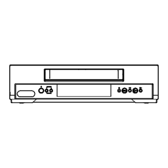
2-4 OPERATING CONTROLS AND FUNCTIONS [ VT-FX340E(UK) ] Front Panel 1. Cassette compartment 2. D (F.FWD) button 3. B (PLAY) button 4. E (REW) button 5. C A ( STOP/EJECT) button 6. I (REC) button 7. Indicator (See below) PROGRAM 8. - Page 13 [ VT-MX310E(UK) ] Front Panel 1. Cassette compartment 2. D (F.FWD) button 3. B (PLAY) button 4. E (REW) button 5. C A (STOP/EJECT) button 6. I ( REC) button 7. Indicator (See below) PROGRAM 8. PROGRAM (o/p) [TRACKING] TRACKING buttons 9.y (OPERATE) button Indicator...
-
Page 14: Maintenance And Inspection
MAINTENANCE AND INSPECTION 3-1 TROUBLESHOOTING Troubleshooting is how to service for the specifying malfunction or poor parts. Detect malfunction or poor parts and service as the following charts. Video problem 1 (No recording Video) RF INPUT LINE INPUT (AV1) Check Video signal at pin 50 of IC301. Check Video signal at pin 48 of IC301. - Page 15 Video problem 2 (No playback Video) Check signal at pin 93 and pin 96 (or pin 87, pin 90) of IC301. Check Video signal at pin 50 of IC501. Cleaning the Video Head. (See page 3-7.) Or check Cylinder Assembly and service it if detective. Check IC301, X301 and line between pin 65 of IC301 and pin 50 of IC501, and service it if detective.
- Page 16 Audio problem 1 (No recording Normal Audio) (with VT-MX310E(UK)) (with VT-MX310E(UK)) RF-INPUT LINE INPUT (AV1) (with VT-FX340E(UK)) (with VT-FX340E(UK)) Check Audio signal at pin 6 or 52 of IC451. Change for Audio-mode(MONO) by AUDIO- SELECT KEY of Remote Controller. Check AV cable, JK101 and Check TU701 and line between JK101 and pin Check SIF signal at pin 2 of CN701.
- Page 17 Audio problem 3 (No recording Hi-Fi Audio) RF-INPUT LINE INPUT (AV1) Check Audio signal at Check A/V cable, JK101 Check TU701 and Check SIF signal at pin pin 6 and pin 52 of IC451. and line between JK101 service it if detective. 2 of CN701.
- Page 18 1] Check for any defective parts while the secondary Power problem rectifying diodes are disconnected (D011, D013 and D014) perform a diode check in both forward and It is highly recommended that a variable isolation reverse directions through a tester. transformer which can monitor current be used.
-
Page 19: Standard Maintenance
3-2 STANDARD MAINTENANCE 3-2-1 Service Schedule of Components h: Hours : Check I: Change Deck Periodic Service Schedule Ref.No. Part Name 1,000 h 2,000 h 3,000 h 4,000 h Cylinder Assembly Loading Motor Assembly Pulley Assembly (HI) B587 Tension Lever Assembly AC Head Assembly B573, B574 Reel S, Reel T... -
Page 20: Cleaning
3-2-2 Cleaning Cleaning of ACE Head Clean the head with a cotton swab. Cleaning of Video Head Procedure Clean the head with a head cleaning stick or chamois 1.Remove the top cabinet. cloth. 2.Dip the cotton swab in 90% Isopropyl alcohol and Procedure clean the ACE head. -
Page 21: Disassembly
DISASSEMBLY 4-1 CABINET DISASSEMBLY INSTRUCTIONS 4-1-1 Disassembly Flowchart (1): Identification (location) No. of parts in the figures (2): Name of the part This flowchart indicates the disassembly steps to gain (3): Figure Number for reference access to item(s) to be serviced. When reassembling, (4): Identification of parts to be removed, unhooked, follow the steps in reverse order. - Page 22 (S-2) (S-1) (S-3) (S-1) (S-2) (S-2) (S-4) [3]VCR Chassis Unit (S-3) (S-2) [1] Top Case (S-1) Fig. 4-1-1 (L-2) (L-2) Fig. 4-1-3 [4] Jack CBA (S-5) Desolder [2] Front Assembly (L-1) Fig. 4-1-2 Fig. 4-1-4...
- Page 23 [8] Cylinder Shield Cylinder Assembly FE Head (S-7) ACE Head SW507 Assembly LD-SW [6] Main CBA [5] Deck Assembly [7] AFV CBA [5] Deck Assembly [VT-FX340E(UK)] Cam Gear [6] Main CBA Hole Shaft (S-6) Hole LD-SW [6] Main CBA Desolder from (S-6) bottom Fig.
-
Page 24: Disassembly/Assembly Procedures Of Deck Mechanism
4-2 DISASSEMBLY/ASSEMBLY PROCEDURES OF DECK MECHANISM Before following the procedures described below, be sure to remove the deck assembly from the cabinet. (Refer to CABINET DISASSEMBLY INSTRUCTIONS on page 4-1.) All the following procedures, including those for adjustment and replacement of parts, should be done in Eject mode;... - Page 25 REMOVAL INSTALLATION STEP START- REMOVE/*UNHOOK/ /LOC. PART ADJUSTMENT Fig. No. UNLOCK/RELEASE/ CONDITION UNPLUG/DESOLDER Loading Arm (SP) (+)Refer to Alignment [34] [26] 4-2-2,4-2-14 Assembly Sec.Page 4-11 Loading Arm (TU) (+)Refer to Alignment 4-2-2,4-2-14 [35] [34] Assembly Sec.Page 4-11 M Brake (TU) Assembly [36] [16],[26] 4-2-1,4-2-15...
- Page 26 Top View [44] [45] [49] [46] [14] [13] [11] [15] [38] [10] [12] [37] [36] [43] [32] [41] [31] [40] [42] Fig. 4-2-1 Bottom View [19] [35] [34] [25] [23] [24] [26] [27] [22] [28] [20] [33] Fig. 4-2-2...
- Page 27 (S-1) (S-1) (L-1) (L-3) (L-2) (P-1) Fig. 4-2-5 [49] Fig. 4-2-3 [50] Pin D (L-12) Pin C Pull up Slide Pin A Pin B Slot A (S-2) Slots B Slot A First, while pushing the locking tab as shown in the right, slide and pull up the right side on [2] to release Pin A and Pin B from the slots A.
- Page 28 (S-4) (S-5) [14] (S-6) [15] Desolder from bottom (S-3) Lead with White Stripe Belt View for A Fig. 4-2-7 Fig. 4-2-9 Adj. Screw [11] [17] (L-4) (L-5) (P-3) [16] [13] [18] [12] (P-4) [10] (P-2) (S-7) Pin of [12] Pin of [10] Fig.
- Page 29 [26] (S-8) (C-3) (S-9) (L-8) [23] (L-7) [24] (C-5) (C-4) (C-2) [28] [25] [29] [30] [19] Cap Belt [27] Fig. 4-2-11 VT-FX340E(UK) only (C-1) turn [20] [22] (L-6) [31] [21] Position of Mode Lever when installed Pin of [37] Pin of [33] Pin of [36] Bottom View [26]...
- Page 30 (P-5) [45] [44] [33] Refer to the Alignment [46] Section, Page 4-11. (L-11) [35] [32] (L-9) [34] Fig. 4-2-16 Fig. 4-2-14 [38] [36] [43] (P-6) turn [39] (L-10) turn [47] [42] [48] Slide turn Fig. 4-2-17 [37] (C-7) [41] (C-6) [40] Fig.
-
Page 31: Alignment Procedures Of Mechanism
4-3 ALIGNMENT PROCEDURES OF MECHANISM The following procedures describe how to align the Alignment 1 individual gears and levers that make up the tape Loading Arm (SP) and (TU) Assembly loading/unloading mechanism. Since information about the state of the mechanism is provided to the Install Loading Arm (SP) and (TU) Assembly so System Control Circuit only through the Mode Switch, that their triangle marks point to each other as... -
Page 32: Adjustment
ADJUSTMENT 5-1 PREPARATION FOR SERVICING 5-1-1 How to Enter the Service Mode About Optical Sensors Caution: An optical sensor system is used for the Tape Start and End Sensors on this equipment. Carefully read and follow the instructions below. Otherwise the unit may operate erratically. -
Page 33: Fixture And Tape For Adjustment
5-2 FIXTURE AND TAPE FOR ADJUSTMENT 1. Alignment Tape 2. Guide Roller Adj. Screwdriver No. 7099052 (MH-2) No. 7099028 3. Flat Screwdriver (Purchase Locally) 5-2-1 How To Use The Fixtures And Tape Item No. Name Part No. Adjustment I Head Switching Point Alignment Tape 7099052 I Tape Interchangeability Alignment... -
Page 34: Electrical Adjustment Instructions
5-3 ELECTRICAL ADJUSTMENT INSTRUCTIONS General Note: "CBA" is an abbreviation for "Circuit Board Assembly." NOTE: Figure 1 1.Electrical adjustments are required after replacing circuit components and certain mechanical parts. It EXT. Syncronize Trigger Point is important to do these adjustments only after all repairs and replacements have been completed. -
Page 35: Mechanical Alignment Procedures
5-4 MECHANICAL ALIGNMENT PROCEDURES Explanation of alignment for the tape to correctly run B. Method to place the Cassette Holder in the tape- starts on the next page. Refer to the information below loaded position without a cassette tape on this page if a tape gets stuck, for example, in the 1. -
Page 36: Tape Interchangeability Alignment
5-4-2 Tape Interchangeability Alignment Note: To do these alignment procedures, make sure that the Tracking Control Circuit is set to the center position every time a tape is loaded or unloaded. (Refer to page 5-7, procedure 1-C, step 2.) Equipment required: Dual Trace Oscilloscope VHS Alignment Tape (MH-2) Guide Roller Adj. -
Page 37: 1-A. Preliminary/Final Checking And Alignment Of Tape Path
1-A. Preliminary/Final Checking and 3. Check to see that the tape runs without creasing at Alignment of Tape Path Take-up Guide Post [4] or without snaking between Guide Roller [3] and ACE Head. (Fig. 5-4-3 and 5- Purpose: 4-5) To make sure that the tape path is well stabilized. 4. -
Page 38: 1-C. Checking/Adjustment Of Envelope Waveform
6. Press CH DOWN button on the unit until the CTL Dropping envelope level at the end of track. waveform has shifted from its original position (not the position achieved in step 5, but the position of CTL waveform in step 4) by approximately -2ms. Make sure that the envelope is simply attenuated (shrinks in height) once CTL waveform passes its original position and is further brought in the minus... -
Page 39: Explodeds Views And Parts List
EXPLODED VIEWS AND PARTS LIST 6-1 EXPLODED VIEWS 6-1-1 Cabinet Section 2L011 2B18 2L011 2L011 2L011 JACK CBA [COMPONENT REPLACEMENT] 2L011 2L012 2L042 2L022 2L021 VT-FX340E(UK) only 2L021 2L021 2L051 2L021 2L022 SENSOR CBA 2L041 [COMPONENT SENSOR CBA REPLACEMENT] 2L021 [COMPONENT REPLACEMENT] AFV CBA... -
Page 40: Deck Mechanism View 1 Section
6-1-2 Deck Mechanism View 1 Section Mark Description Floil G-684G or Multemp MH-D (Blue grease) SLIDUS OIL #150 B494 L1467 L1191 B553 B411 B567 L1053 B410 L1051 Chassis Assembly Top View (Lubricating Point) B501 L1450 L1450 L1466 B121 B126 B492 B571 VT-FX340E(UK) only Chassis Assembly... -
Page 41: Deck Mechanism View 2 Section
6-1-3 Deck Mechanism View 2 Section Mark Description Floil G-684G or Multemp MH-D (Blue grease) SLIDUS OIL #150 SANKOUL FG84M (Yellow grease) B587 B521 B487 B416 B591 B590 B499 B148 B573 B508 B574 L1406 B592 B585 B518 B564 B522 B414 B572 B565 L1151... -
Page 42: Deck Mechanism View 3 Section
6-1-4 Deck Mechanism View 3 Section Mark Description L1321 Floil G-684G or Multemp MH-D (Blue grease) B347 SLIDUS OIL #150 L1321 B355 B354 B483 B425 B482 B562 B300 B563 B313 B529 B360 B359 B361 B555 B303 B514... - Page 43 THE UPDATED PARTS LIST FOR THIS MODEL IS AVAILABLE ON ESTA...
-
Page 44: Schematic, Circuit Board And Block Diagrams
SCHEMATIC, CIRCUIT BOARD AND BLOCK DIAGRAMS 1 SCHEMATIC DIAGRAMS / CBA’S AND TEST POINTS Standard Notes Notes: WARNING 1. Do not use the part number shown on these draw- ings for ordering. The correct part number is shown Many electrical and mechanical parts in this chassis in the parts list, and may be slightly different or have special characteristics. - Page 45 LIST OF CAUTION, NOTES, AND SYMBOLS USED IN THE SCHEMATIC DIAGRAMS ON THE FOLLOWING PAGES: 1. CAUTION: FOR CONTINUED PROTECTION AGAINST FIRE HAZARD, REPLACE ONLY WITH THE SAME TYPE FUSE. 2. CAUTION: Fixed Voltage (or Auto voltage selectable) power supply circuit is used in this unit. If Main Fuse (F1001) is blown, first check to see that all components in the power supply circuit are not defec- tive before you connect the AC plug to the AC power supply.
- Page 46 2 WIRING DIAGRAMS AC CORD ANT-IN ANT-OUT VT-FX340E(UK) CN701 SENSOR CBA 1 NU 3 GND TU-AUDIO(R) AFV CBA SENSOR CBA TU-AUDIO(L) P-ON+5V P-ON+5V (DECK ASSEMBLY) IIC-BUS SCL IIC-BUS SDA ACE HEAD ASSEMBLY CL287 CL504 AUDIO AE-H AE-H ERASE HEAD AE-H/FE-H AE-H/FE-H A-COM A-COM...
-
Page 47: Schematic Diagrams/Cba's And Test Points . 1 2 Wiring Diagrams
3 SCHEMATIC DIAGRAMS 3-1 Main 1/7 Schematic Diagram... -
Page 48: Main 2/7 & Sensor Schematic Diagrams
3-2 Main 2/7 & Sensor Schematic Diagrams... -
Page 49: Main 3/7 Schematic Diagram
3-3 Main 3/7 Schematic Diagram... -
Page 50: Main 4/7 & Jack Schematic Diagram
3-4 Main 4/7 & Jack Schematic Diagram... -
Page 51: Main 5/7 Schematic Diagram
3-5 Main 5/7 Schematic Diagram CAUTION ! Fixed voltage ( or Auto voltage selectable ) power supply circuit is used in this unit. CAUTION ! NOTE : If Main Fuse (F1001) is blown, check to see that all components in the power supply For continued protection against fire hazard, The voltage for parts in hot circuit is measured using circuit are not defective before you connect the AC plug to the AC power supply. -
Page 52: Main 6/7 Schematic Diagram ( Vt-Fx340E(Uk) )
3-6 Main 6/7 Schematic Diagram ( VT-FX340E(UK) ) -
Page 53: Main 7/7 Schematic Diagram
3-7 Main 7/7 Schematic Diagram... -
Page 54: Afv Schematic Diagram ( Vt-Fx340E(Uk) )
3-8 AFV Schematic Diagram ( VT-FX340E(UK) ) -
Page 55: Waveforms
4 WAVEFORMS (TP301 of Main CBA) UPPER (TP502 of Main CBA) LOWER C-PB 10mV x 10 RF-SW 0.5V x 10 5msec (J23 of Main CBA) UPPER (TP502 of Main CBA) LOWER V-OUT 0.1V x 10 RF-SW 0.5V x 10 50usec (J23 of Main CBA) V-OUT E-E 10usec... -
Page 56: Circuit Board Diagrams
5 CIRCUIT BOARD DIAGRAMS 5-1 Main CBA Top View & Sensor CBA Top View CAUTION ! BECAUSE A HOT CHASSIS GROUND IS PRESENT IN THE POWER CAUTION ! For continued protection against fire hazard, SUPPLY CIRCUIT , AN ISOLATION TRANSFORMER MUST BE USED. Fixed voltage ( or Auto voltage selectable ) power supply circuit is used in this unit. -
Page 57: Main Cba Bottom View
5-2 Main CBA Bottom View CAUTION ! BECAUSE A HOT CHASSIS GROUND IS PRESENT IN THE POWER CAUTION ! For continued protection against fire hazard, SUPPLY CIRCUIT , AN ISOLATION TRANSFORMER MUST BE USED. Fixed voltage ( or Auto voltage selectable ) power supply circuit is used in this unit. replace only with the same type fuse. -
Page 58: Jack Cba Top / Bottom View
5-3 Jack CBA Top / Bottom View Jack CBA Top View Jack CBA Bottom View... -
Page 59: Afv Cba Top / Bottom View ( Vt-Fx340E(Uk) )
5-4 AFV CBA Top / Bottom View ( VT-FX340E(UK) ) AFV CBA Top View AFV CBA Bottom View... -
Page 60: Block Diagrams
6 BLOCK DIAGRAMS 6-1 Servo/System Control Block Diagram IC501 TP507 (SERVO/SYSTEM CONTROL) MAIN CBA AL+5V SENS-INH KEY- 1 RS501 SWITCH SW507 D502 REMOTE LD-SW S-LED REMOCON-IN KEY- 2 SENSOR SWITCH FP562 LED DISPLAY IC561 (LED DISPLAY) AL+5V LD-SW CTL(+) Q504 CTL(-) ST-S ST-S... -
Page 61: Video Block Diagram
6-2 Video Block Diagram REC-VIDEO SIGNAL PB-VIDEO SIGNAL MODE: SP/REC IC640 (VPS) MAIN CBA DAVN-L FROM/TO DAVN-L IC501 (OSD) IIC-BUS SDA SERVO/SYSTEM IIC-BUS SDA CONTROL BLOCK IIC-BUS SCL IIC-BUS SCL VPS-V CHARACTER IC301 Q351 BUFFER (Y/C SIGNAL PROCESS) (DECK ASSEMBLY) SERIAL Y. -
Page 62: Audio Block Diagram (Vt-Mx310E(Uk))
Audio Block Diagram (VT-MX310E(UK)) PB-AUDIO SIGNAL REC-AUDIO SIGNAL Mode : SP/REC TU701(TUNER UNIT) JACK CBA MAIN CBA AUDIO JK101 TU-AUDIO A-IN1(R) CL101 CL151 A-IN1(L) A-IN1 A-OUT1(R) A-OUT1 A-OUT1(L) IC151 (SWITCHING) JK102 PB/EE A-IN2(R) CL102 CL152 Q151 PB/EE A-IN2(L) A-IN2 BUFFER PB/EE A-OUT2 A-OUT2(R) -
Page 63: Audio Block Diagram (Vt-Fx340E(Uk))
Audio Block Diagram (VT-FX340E(UK)) PB-AUDIO SIGNAL REC-AUDIO SIGNAL Mode : SP/REC MAIN CBA N-A-PB FROM/TO Hi-Fi N-A-REC AUDIO BLOCK IC301 (AUDIO SIGNAL PROCESS) TUNER PB-ON LINE MUTE (DECK ASSEMBLY) SP/LP-ON ACE HEAD ASSEMBLY REC-ON Q401 CL287 CL504 A-PB/REC AUDIO 4 A-PB/REC Q402 HEAD A-COM... - Page 64 (VT-FX340E(UK)) 6-5 Hi-Fi Audio Block Diagram PB-AUDIO SIGNAL REC-AUDIO SIGNAL Mode : SP/REC JACK CBA MAIN CBA JK101 CL101 CL151 A-IN1(R) A-IN1(R) A-IN1(L) A-IN1(L) A-OUT1(R) A-OUT1(R) 6 A-OUT1(L) A-OUT1(L) 12 JK102 CL102 CL152 A-IN2(R) A-IN2(R) A-IN2(L) A-IN2(L) A-OUT2(R) A-OUT2(R) 6 A-OUT2(L) A-OUT2(L) 11 AFV CBA...
-
Page 65: Power Supply Block Diagram
6-6 Power Supply Block Diagram NOTE : CAUTION CAUTION ! FOR CONTINUED PROTECTION AGAINST FIRE HAZARD, Fixed voltage (or Auto voltage selectable ) power supply circuit is used in this unit. The voltage for parts in hot circuit is measured using If Main Fuse (F001) is blown, check to see that all components in the power supply REPLACE ONLY WITH THE SAME TYPE T1.6AL/250V FUSE. -
Page 66: System Control Timing Charts
7 SYSTEM CONTROL TIMING CHARTS Mode SW : LD-SW LD-SW Position detection A/D Input voltage Limit Symbol (Calculated voltage) 3.76V~4.50V (4.12V) 4.51V~5.00V (5.00V) 0.00V~0.25V (0.00V) 1.06V~1.50V (1.21V) 0.66V~1.05V (0.91V) 1.99V~2.60V (2.17V) 1.51V~1.98V (1.80V) 3.20V~3.75V (3.40V) 0.26V~0.65V (0.44V) 4.51V~5.00V (5.00V) 2.61V~3.19V (2.97V) Note: Note:... - Page 67 [ VT-FX340E(UK) ] Still/Slow Control Frame Advance Timing Chart 1) SP Mode 18 RF-SW The first rise of RF-SW after a rise in F-AD signal F-AD (Internal Signal) "H" "H" "Z" C-DRIVE "L" "L" Stop detection (T2) Acceleration Detection (T1) Slow Tracking Value PB CTL Reversal Limit Value...
- Page 68 2) LP Mode 18 RF-SW The first rise of RF-SW after a rise in F-AD signal F-AD (Internal Signal) "H" "H" "Z" C-DRIVE "L" "L" Stop detection (T2) Acceleration Detection (T1) Slow Tracking Value PB CTL Reversal Limit Value 20ms 78 C-F/R 16 H-A-SW 15 ROTA...
- Page 69 1. EJECT (POWER OFF) -> CASSETTE IN (POWER ON) -> STOP(B) -> STOP(A) -> PLAY -> RS -> FS -> PLAY -> STILL -> PLAY -> STOP(A) PIN NO. LD-SW CL/SS 0.3s 0.3s LM-FWD "M" 0.2s /REV 0.2s 0.2s 0.2s 0.2s "Z"...
- Page 70 2. STOP(A) -> FF -> STOP(A) -> REW -> STOP(A) -> REC -> PAUSE -> PAUSE or REC -> STOP(A) -> EJECT PIN NO. LD-SW CL/SS LM-FWD "M" /REV 0.2s 0.2s 0.2s 0.2s 0.2s 0.2s "Z" C-DRIVE 20ms 0.1s 20ms 20ms 0.4s 0.4s...
- Page 71 1. EJECT (POWER OFF) -> CASSETTE IN (POWER ON) -> STOP(B) -> STOP(A) -> PLAY -> RS -> FS -> PLAY -> STILL -> PLAY -> STOP(A) PIN NO. LD-SW CL/SS 0.3s 0.3s LM-FWD "M" /REV 0.2s 0.2s 0.2s 0.2s 0.2s "Z"...
- Page 72 2. STOP(A) -> FF -> STOP(A) -> REW -> STOP(A) -> REC -> PAUSE -> PAUSE or REC -> STOP(A) -> EJECT PIN NO. LD-SW CL/SS LM-FWD "M" /REV 0.2s 0.2s 0.2s 0.2s 0.2s 0.2s "Z" C-DRIVE 20ms 0.1s 20ms 20ms 0.4s 0.4s...
-
Page 73: Ic Pin Function Descriptions
8 IC PIN FUNCTION DESCRIPTIONS Comparison Chart of Models and Marks Signal Active Mark Function Name Level Model Mark Not Used VT-FX340E(UK) Video Head OUT H-A-SW Amp Switching VT-MX310E(UK) Pulse Not Used IC501( SERVO / SYSTEM CONTROL IC ) Head Amp H-A-COMP Comparator “H”... - Page 74 Signal Active Signal Active Mark Function Mark Function Name Level Name Level OUT Xcout Sub Clock LED Clock OUT DRV-DATA Driver IC Control Data Main Clock LED Clock Input OUT DRV-STB Driver IC Chip Select Signal Main Clock OUT Xout Input LED Clock OUT DRV-CLK...
- Page 75 Signal Active Mark Function Name Level AMPVREF V-Ref for CTL V-Ref for CTL AMPVREFin P80/C P80/C Terminal Playback/ OUT CTL - Record Control Signal (-) Playback/ OUT CTL + Record Control Signal (+) CTL AMP AMPC Connected Terminal To Monitor for CTLAMPout CTL AMP Output...
-
Page 76: Lead Identifications
9 LEAD IDENTIFICATIONS 2SC1815-Y(TPE2) LC74793JM-TRM BN1L4M-T 2SC1815-GR(TPE2) BN1F4M-T 2SC3266-Y (TPE2) BA1F4M-T 2SC2120-Y(TPE2) KTA1266(GR) KTC3203(Y) KTC3199(Y,GR,BL) 2SC1815-BL(TPE2) 2SC2785(J.H.F.K) 2SA1020(Y) KRA103M KTC3205(Y) KRC103M 2SA1015-GR(TPE2) KTA1281(Y) E C B E C B QSZAB0RMB168 LA71750AM-MTB BU4052BCF-E2 BR24C02F-W TC4053BF(N) CAT24WC02JI CD4053BCSJX LTV-817(B,C)-F KTA1504GR-RTK 2SK3566 KTA1504Y-RTK PT-6958-FN-TP KTC3875Y-RTK RN1511(TE85R) - Page 77 Fax: +46 (0) 8 562 711 13 Tel: +39 02 38073415 Servizio Clienti Email: csgswe@hitachi-eu.com Fax: +39 02 48786381/2 Email: customerservice.italy@hitachi-eu.com HITACHI EUROPE S.A.S HITACHI EUROPE LTD (Norway) AB Lyon Office STRANDVEIEN 18 B.P. 45, 69671 BRON CEDEX 1366 Lysaker FRANCE...
Need help?
Do you have a question about the VTFX340EUK and is the answer not in the manual?
Questions and answers