Table of Contents
Advertisement
Quick Links
User Manual EPT USB PLD Dev System
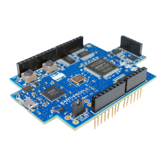
UNOPROLOGIC
USB CPLD DEVELOPMENT SYSTEM
Data Sheet
The UnoProLogic is a part of the EPT USB/PLD development system. It provides an innovative
method of developing and debugging the users microcontroller code. It can also provide a high
speed data transfer mechanism between microcontroller and Host PC.
The UnoProLogic board is equipped with an Altera 5M570 PLD; which is programmed using the
Altera Quartus II software. The PLD has 570 Logic Elements which is equivalent to 440
Macrocells. An on board 66 MHz oscillator is used by the EPT-Active-Transfer-Library to
provide data transfer rates of 0.1 Mega Bytes per second. The EPT-Active-Transfer-Library
provides control communication between the objective device and the PLD. Data transfer during
the objective device checkout between the PC and the PLD program is available via the Hyper
Serial Port. The board also includes the following parts.
Page 1
Advertisement
Table of Contents

Related Manuals for EarthPeople Technology UnoProLogic

Summary of Contents for EarthPeople Technology UnoProLogic
- Page 1 USB CPLD DEVELOPMENT SYSTEM Data Sheet The UnoProLogic is a part of the EPT USB/PLD development system. It provides an innovative method of developing and debugging the users microcontroller code. It can also provide a high speed data transfer mechanism between microcontroller and Host PC.
-
Page 2: Block Diagram
• Four Green LED’s accessible by the user • Two PCB switches accessible by the user • All connectors to stack into the Arduino Uno • USB to Serial FT2232H Dual Channel Chip. 1 Block Diagram Figure 1 UNOPROLOGIC Block Diagram Page 2... - Page 3 User Manual EPT USB PLD Dev System Figure 2 UnoProLogic Component Callouts Page 3...
-
Page 4: Mechanical Dimensions
User Manual EPT USB PLD Dev System 2 Mechanical Dimensions 3 Pin Mapping Pin Mapping between Connectors, MAXV CPLD and User code Component Net Name Pin on CPLD Signal in EPT Project Pinout 66MHz Oscillator GCLK CLK_66MHZ Reset Page 4... - Page 5 User Manual EPT USB PLD Dev System JTAG_TCK (Not In Project) JTAG_TDI (Not In Project) JTAG_TDO (Not In Project) JTAG_TMS (Not In Project) BD_INOUT0 BD_INOUT1 BD_INOUT2 BD_INOUT3 BD_INOUT4 BD_INOUT5 BD_INOUT6 BD_INOUT7 BC_IN1 BC_IN0 BC_OUT2 BC_OUT1 BC_OUT0 SW_USER_1 SW_USER_1 SW_USER_2 SW_USER_23 TR_DIR_1 TR_DIR_1 Page 5...
- Page 6 User Manual EPT USB PLD Dev System TR_DIR_2 TR_DIR_2 TR_DIR_3 TR_DIR_3 TR_OE_1 TR_OE_1 TR_OE_2 TR_OE_2 TR_OE_3 TR_OE_3 LED_GR_1_N LED0 LED_GR_2_N LED1 LED_GR_3_N LED2 LED_GR_4_N LED3 ADC_EOC ADC_EOC ADC_CS ADC_CS ADC_SCLK ADC_CLK ADC_DIN ADC_MOSI ADC_DOUT ADC_MISO ADC_CNVST ADC_CNVST LB_IOH0 LB_IOH1 LB_IOH2 LB_IOH3 LB_IOH4 LB_IOH5...
-
Page 7: Pushbutton Switches
LB_IOL2 LB19 LB_IOL3 LB20 LB_IOL4 LB21 LB_IOL5 LB22 LB_IOL6 LB23 LB_IOL7 4 Pushbutton switches There are two pushbutton switches on the UnoProLogic. Both are momentary contact switches. They include a 1uF cap to ground to debounce both switches. Page 7... - Page 8 User Manual EPT USB PLD Dev System Component Net Name Pin on CPLD Signal in EPT Project Pinout SW_USER_1 SW_USER_1 SW_USER_2 SW_USER_23 Page 8...
- Page 9 User Manual EPT USB PLD Dev System 5 LEDs The UnoProLogic includes four Green LEDs. The LEDs are connected to the CPLD in a “Current Sink” configuration. This means the LEDs Anodes are permanently connected to +3.3V. Each Cathode side of the LEDs are connected to an individual I/O of the CPLD. In order to turn on the LED, the CPLD I/O must apply a low signal.
- Page 10 User Manual EPT USB PLD Dev System 6 Host PC Connection The UnoProLogic includes an LED that signifies the connection of the board with the Host PC. The connect LED has the word “CONNECT” in silkscreen next to the LED. This LED will only...
- Page 11 Host PC has correctly enumerated the USB device (FT2232HQ chip). When this LED is lit up it can tell the user three things: • Power has been applied to the UnoProLogic via USB • The FT2232HQ chip is working properly •...
- Page 12 User Manual EPT USB PLD Dev System I/O’s are organized as three 8 bit directional ports. Each port must be defined as input or output. This means that all 8 bits of a port will point in the same direction, depending on the direction bit of the transceiver.
-
Page 13: Electrical Characteristics
User Manual EPT USB PLD Dev System This 8-bit (octal) noninverting bus transceiver contains two separate supply rails; B port has VCCB, which is set at 3.3 V, and A port has VCCA, which is set at 5 V. This allows for translation from a 3.3-V to a 5-V environment, and vice versa. -
Page 14: Timing Characteristics
User Manual EPT USB PLD Dev System 7.2 Timing Characteristics 7.3 Description 24 mA drive at 3-V supply – Good for heavier loads and longer traces Low VIH – Allows 3.3-V to 5-V translation Page... -
Page 15: Analog Connector
User Manual EPT USB PLD Dev System 8 Analog connector The UnoMax includes a six pin analog input connector. This connector provides a path from the pins to the input of the four Op-Amp buffers. Each Op-Amp includes a 1MHz low pass filter. Each Op-Amp provides a buffer for the analog signals to the ADC inputs. -
Page 16: Analog To Digital Converter
User Manual EPT USB PLD Dev System 9 Analog to Digital Converter The EPT 5M57-AP-U2 has an onboard Four Channel, 10 Bit, 300 KSamples/second Analog to Digital Converter. It has a serial SPI communications that allow the host to send setup commands and retrieve the sampled data. - Page 17 User Manual EPT USB PLD Dev System 5, 6, 7 N.C. No Connection CONVST Active – low Conversion Start Input Reference Input Ground Power Input Active Low Chip Select Input. When CS is Low the interface is enabled. When CS is high MOSI is high impedance SCLK Serial Clock input.
- Page 18 User Manual EPT USB PLD Dev System 9.1 Electrical Characteristics 9.2 3-Wire Serial Interface The MAX11618–MAX11621/MAX11624/MAX11625 feature a serial interface compatible with SPI/QSPI and MICROWIRE devices. For SPI/QSPI, ensure the CPU serial interface runs in master mode so it generates the serial clock signal. Select the SCLK frequency of 10MHz or less, and set clock polarity (CPOL) and phase Page...
- Page 19 User Manual EPT USB PLD Dev System (CPHA) in the μP control registers to the same value. The MAX11618 operate with SCLK idling high or low, and thus operate with CPOL = CPHA = 0 or CPOL = CPHA = 1. Set CS low to latch input data at DIN on the rising edge of SCLK.
- Page 20 User Manual EPT USB PLD Dev System Page...
- Page 21 User Manual EPT USB PLD Dev System Register Descriptions The MAX11618 communicate between the internal registers and the external circuitry through the SPI-/QSPI-compatible serial interface. Table 1 details the registers and the bit names. Tables 2–5 show the various functions within the conversion register, setup register, averaging register, Page...
- Page 22 User Manual EPT USB PLD Dev System and reset register. Conversion Register Select active analog input channels per scan and scan modes by writing to the conversion register. Table 2 details channel selection and the four scan modes. Request a scan by writing to the conversion register when in clock mode 10 or 11, or by applying a low pulse to the CNVST pin when in clock mode 00 or 01.
- Page 23 User Manual EPT USB PLD Dev System Setup Register Write a byte to the setup register to configure the clock,reference, and power-down modes. Table 3 details the bits in the setup register. Bits 5 and 4 (CKSEL1 and CKSEL0) control the clock mode, acquisition and sampling, and the conversion start.
- Page 24 User Manual EPT USB PLD Dev System Averaging Register Write to the averaging register to configure the ADC to average up to 32 samples for each requested result, and to independently control the number of results requested for single-channel scans. Table 2 details the four scan modes available in the conversion register. All four scan modes allow averaging as long as the AVGON bit, bit 4 in the averaging register, is set to 1.
- Page 25 User Manual EPT USB PLD Dev System Reset Register Write to the reset register (as shown in Table 5) to clear the FIFO or to reset all registers to their default states. Set the RESET bit to 1 to reset the FIFO. Set the reset bit to zero to return the MAX11618 to the default power-up state.
- Page 26 11 Oscillator There is a 66MHz oscillator on the UnoProLogic, This oscillator has the following Vendor and 1. 66MHz, Renesas Electronics America Inc; P/N: XLH536066.000000I This oscillators are connected to the Global Clock inputs on the FPGA. Both devices provide stable clock for the FPGA’s internal DLL’s.
- Page 27 User Manual EPT USB PLD Dev System the net connected to the FPGA pin. Component Net Name Pin on CPLD Signal in EPT Project Pinout 66MHz Osc GCLK1 CLK_66MHZ XLH536066.000000I PARAMETERS MAX (unless otherwise noted) Frequency 66MHz Supply Voltage (VDD) 3.3V Page...
-
Page 28: Usb To Serial
User Manual EPT USB PLD Dev System Input Current (IDD) >50.000 ~ 67.000MHz 25 mA Standby Current 10 µA Output Symmetry (50% VDD) >50.000 ~ 170.000MHz 40% ~ 60% Rise/Fall Time (10%/90% VDD Levels) (TR/TF) 1.000 ~ 80.000MHz 6 nS Output Voltage (VOL) 10% VDD (VOH) - Page 29 The UnoProLogic can be powered from the USB bus of a Host/PC or the optional barrel connector. The USB supplies a maximum of +5V @ 500mA’s. The components of the UnoProLogic must share this power with the user code that will run inside the FPGA along with any external power use.
- Page 30 User Manual EPT USB PLD Dev System 74LVC8245 15mA (All Transceivers eight I/O’s active) USB Chip FT2232H 60 mA (no sink current supplied to I/O’s) 93LC56 2 mA (write EEPROM current) 1 mA (read current) 66MHz CB3LV-3I-66M0 10 mA Oscillator ADC Four MAX11618EEE+ 17 mA...
- Page 31 User Manual EPT USB PLD Dev System +1.8V Power MCP1725- 70mA Supply 1802E +3.3V Power MCP1725- 215mA Supply 3302E Total 285mA * Theoritical Values only. This data needs to be validated Page...
Need help?
Do you have a question about the UnoProLogic and is the answer not in the manual?
Questions and answers