
Related Manuals for Marel M6000

Summary of Contents for Marel M6000
- Page 1 Hardware Manual Version 2.00 M6000 Controller Marel hf. Austurhraun 9 i IS-210 Gardabaer i ICELAND Tel: +354 563 8000 i Fax: +354 563 8001 info@marel.is i www.marel.com...
- Page 2 Information in this document is subject to change without further notice, and does not represent a commitment by Marel hf. No part of this document may be reproduced, stored in a retrieval system, or transmitted in any form or by any means, electronic, mechanical, photocopying or otherwise, without the prior written permission of Marel hf.
- Page 3 Do Not drop the M6000 Controller. Some types of the M6000 contain a hard disk drive which is sensitive to shock. ATTENTION! The M6000 is a Class I equipment and MUST have a protective earthing connection for safe operation.
- Page 4 Marel hf.
-
Page 5: Table Of Contents
Contents ................3 ECHNICAL PECIFICATIONS Introduction ...................5 BOUT ANUAL Improvements ......................5 Warranty Information ....................5 The M6000 Controller M6000 ....................7 BOUT THE ....................7 NITIAL NSPECTION ......................7 LEANING ..................10 NTERFACE M6000........11 ONNECTING EADY MADE ABLES NSIDE ....................12 ARDWARE ....................15 ISPLAY ETTINGS M6000 ..............16... - Page 6 • Contents M6000 Controller...
-
Page 7: Technical Specifications
Technical Specifications Manufacturer: Marel hf. Dimensions: Outer Dimensions: 534 x 510 x 120 mm (W x H x D), brackets included Weight: 10 kg (22 lb) Construction: Material: AISI 316 stainless steel Environment protection: IEC 529-IP67 washdown environment (NEMA 6) Cleaning: Wash with water and ordinary soap. - Page 8 4 • Technical Specifications M6000 Controller...
-
Page 9: Introduction
The M6000 Controller, Hardware Manual contains descriptions of the controller’s basic components and instructions in how to use its basic functions. It is intended for your assistance in installing and operating the M6000 controller. Improvements You can help improve this manual and the equipment you purchased. If you find any errors in the manual, please let us know. - Page 10 6 • Introduction M6000 Controller...
-
Page 11: The M6000 Controller
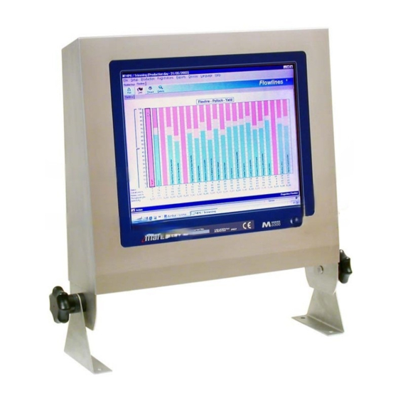
The M6000 Controller About the M6000 The M6000 industrial controller is built on a PC-compatible architecture. The controller is encased in a water-resistant stainless steel housing rated to IP67 standards. The controller’s user-friendly display is a 15” 1024 x 768 pixel LCD color monitor and a very tough touch screen designed to withstand the harshest treatment. - Page 12 (KOH) or caustic soda (NaOH). Because of its corrosive effects, caustic soda is not a desirable detergent for the M6000. If possible, use detergent solutions with KOH instead. Always use detergents according to the detergent manufacturer’s instructions.
- Page 13 Training staff It is important that new cleaning personnel receive proper training and are made aware of areas on the equipment which are difficult to clean. Hardware Manual, vers. 2.00 The M6000 Controller • 9...
-
Page 14: The User Interface
Because the controller is designed to run any Windows® or Linux® based applications , the M6000 user interface in the context of this manual is the touch screen itself. The rating plate at the bottom of the touch screen shows the controller’s production serial number, voltage and current rating. -
Page 15: Connecting Ready-Made Cables Inside M6000
Connecting Ready-made Cables Inside M6000 The M6000 user (installer) can put ready-made cables with connectors through the glands on the M6000. This is easily done, for example with Ethernet cables, USB cables and keyboard cables, because the glands are equipped with a split insert specifically intended for such cases (see Figure 2). -
Page 16: The Hardware
The M6000 Hardware Figure 3 M6000 Controller, inside view. The hardware inside the M6000 consists of two printed circuit boards and a TFT display. The hard disk and the 110-230 Vac power supply are optional components, available in some M6000 controller types. - Page 17 PS/2 mouse data output connector from the touch screen • Push buttons for screen adjustments • Display connector for connecting the TFT display Figure 5 M6000 Controller, description of internal components and connections. Hardware Manual, vers. 2.00 The M6000 Controller • 13...
- Page 18 CPU board. Figure 6 and Figure 7 show the power-on switch cable connection. Figure 6 M6000 Controller, power-on switch cable connection between the V6000 board and the CPU board. Figure 7 M6000 Controller, power-on switch cable connection on the CPU board.
-
Page 19: Display Settings
PHASE push button for adjusting the display focus. In most cases it is not necessary for the M6000 user to center the picture or adjust the horizontal size or focus of the picture. These adjustments are already done at the factory. -
Page 20: Applying Power To The M6000
Figure 9 M6000 Controller, screen adjustments. For best results when adjusting the focus on the M6000 display, use the file C:\M6000_WIN_TOOLS\BackGround_Pictures\test [1].bmp as a centered background picture and press the button in steps until PHASE the center of the test [1].bmp picture is clear. -
Page 21: Entering Bios Setup On M6000
Figure 12 M6000 Controller, the heater is located under the display. Entering BIOS Setup On M6000 To enter BIOS setup on M6000 it is necessary to open the M6000 cabinet by loosening the two screws under the cabinet, and to connect a PC keyboard with the PS/2 keyboard interface on the CPU board (see Figure 4). -
Page 22: The Operating System On The M6000
On some M6000 models the Windows operating system is preinstalled. In such cases a “Certificate of Authenticity” label for the Windows operating system is affixed inside the M6000 as shown in Figure 13. The label is kept inside the housing to prevent it from being ruined during cleaning. - Page 23 If the M6000 is delivered with a Windows operating system, the setup program for the touch screen is delivered with the M6000 on a CD-ROM as well as being installed on the hard disk drive under: C:\M6000_WIN_TOOLS\TouchScreen_Driver_WinXP_Sp2\UniWinDri ver620a\ To install the touch screen driver run: To set up the touch screen driver, select the controller type TSHARK-10/12 PS/2 as shown in Figure 14.
- Page 24 For optimal calibration results we recommend that you select a 20 point calibration type as shown in Figure 16. Figure 16 M6000 Controller, touch screen controller calibration type. After selecting the calibration type, proceed with the calibration process by pressing the Calibration target, shown in Figure 15.
- Page 25 Open Windows Explorer, go to the Tools menu and select Folder Options. • The dialog box in Figure 19 appears. • Select Single-click to open an item, and press OK. Figure 19 M6000 Controller, replacing double-click with single-click. Hardware Manual, vers. 2.00 The M6000 Controller • 21...
- Page 26 Figure 20 shows how to enable a sound when the screen is touched. Figure 20 M6000 Controller, enabling touch screen sound. 22 • The M6000 Controller M6000 Controller...
-
Page 27: Index
ID reader, 10 IDE (ATA) connector, 13 IDE connector, 14 Indicator, 7 Cabinet heater, 17 Initial start of M6000, 16 Calibrating the screen, 19 Inputs, power, 13 Certificate of Authenticity, 18 Inspection for damages, 7 Changing double-click to single-click, 21... - Page 28 Voltage, 3 adjustments, 15 calibration, 19 settings, 18 Serial I/O, 3 Warranty, 5 Serial number, 10, 18 Weight, 3 Sound, enabling for touch screen, 22 Windows, 18 Status indicator, 10 Windows, OS, 10 Test picture, 16 24 • Index M6000 Controller...
Need help?
Do you have a question about the M6000 and is the answer not in the manual?
Questions and answers