
Subscribe to Our Youtube Channel
Related Manuals for Time Machines TM2500C


Summary of Contents for Time Machines TM2500C
- Page 1 TM2000B / TM2500C PTP and NTP Time Server GPS Time Sourced Installation and Operation Manual v0.4.5 and v0.6.1...
-
Page 2: Table Of Contents
3.4.4 Satellites Used........................7 3.4.5 GPS Fix...........................7 3.4.6 NTP Lookups..........................7 3.4.7 Holdover Time........................7 3.4.8 MAC............................7 3.4.9 Uptime............................7 3.4.10 OCXO Correction.........................7 3.4.11 DPLL Status (TM2500C Only)....................8 3.4.12 DPLL Temp (TM2500C Only).....................8 3.4.13 Version..........................8 3.4.14 Satellites..........................8 3.4.15 NTP Peers..........................8 3.4.16 PTP Clients...........................9 3.5 Update Page..........................10... - Page 3 3.6 SNMP Setup..........................11 3.6.1 MIB File-Download TMI-COMMON-SHI.txt..............11 3.6.2 Enable...........................11 3.6.3 SNMP Trap Version......................11 3.6.4 Notification Method......................11 3.6.5 Trap Receiver IP Address.....................12 3.6.6 SNMP V2 Community Name....................12 3.6.7 SNMP V3 R/W User Name....................12 3.6.8 SNMP V3 R/W Password.....................12 3.6.9 SNMP V3 Engine ID......................12 3.7 NTP Settings Page........................13 3.7.1 Start / Stop NTP Server......................13 3.7.2 Allow 2D Fix for NTP......................14...
- Page 4 6.3 Antenna Specifications.........................23 6.4 TM2500C OCXO Timing Information / Specifications...............23 TimeMachines, Inc. 300 S68 St Place, Suite 100 Lincoln, NE 68510 402-486-0511 Engineered and Manufactured in Lincoln, NE, USA Rev 0.6.1 1-1-2022...
-
Page 5: Introduction
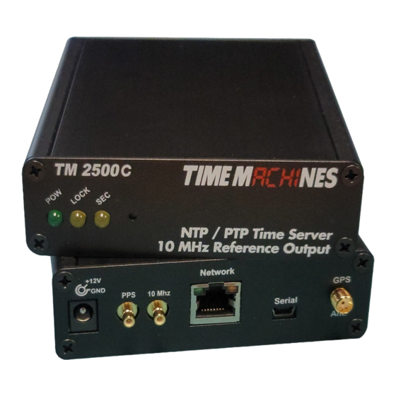
OCXO (Oven controller oscillator) that allows the unit to serve accurate time beyond loss of the GPS antenna signal. The TM2500C differs from the TM2000B in that is has a pair of SMB outputs to allow for 1PPS and a synchronized 10MHz reference signal to be output from the device. -
Page 6: Installation
2 Installation 2.1 Location To receive GPS signals the Time Server's antenna must be located in a location where it can “see” the sky. The GPS module itself is highly sensitive and able to “see” the GPS satellite signals from within many structures. -
Page 7: 10Mhz (2500C Only)
of the GPS receiver. It is a 50% duty cycle output where the positive rising edge denotes the second boundary. The GPS receiver 1PPS output is specified at +/10 nano-seconds. Best results are achieved with an outdoor antenna with a full 360 degree view of the sky. Degraded signal quality will degrade the precision of this output. -
Page 8: Settings Page
3.3 Settings Page 3.3.1 TM2X00 Name This is a generic entry that has no effect on the TM2X00 operation other than to allow the user to enter a name for the device to help recognize it when parameter updates are required. 3.3.2 IP Address The IP address of the unit set to by entering a standard IPv4 dotted quad in this field. -
Page 9: Netmask
setting. This is used by the PTP functions to advertise the presence of the server. Clicking the Submit button will set the entered IP parameters. THIS IS NOT the address to point NTP and PTP clients at, they should given the IP Address. 3.3.4 Netmask The Netmask entry determines what addresses are on the local network and what addresses are reached through the Gateway. -
Page 10: Password
device. These should NOT be changed until another leap second is announced. When that occurs, the Current setting will be changed to 37, the Day adjusted to midnight of the day it will occur (always June 30 , or December 31 ), and the Next setting will be updated as well to the new number of leap seconds. -
Page 11: Time Source
The status page is an information only page. It shows the various pieces of information about the current working state of the device. 3.4.1 Time Source This field displays the current source of time. It can be GPS, Peer Time Server, or Manually set. 3.4.2 Location Location shows the latitude and longitude of the device itself based on the GPS receiver. -
Page 12: Dpll Status (Tm2500C Only)
SMB connectors. The DPLL does require a little bit of time after 2D lock to converge and start outputting signals. 3.4.12 DPLL Temp (TM2500C Only) This is the temperature of the Digital PLL chip on the TM2500C circuit board. It has an operation range of -40C to +85C. 3.4.13 Version Displays current software version running on device. -
Page 13: Ptp Clients
Stratum – This field shows the stratum level being reported by the peer time server • RootD – This is the root delay value of the peer time server. This is the time servers reported • delay from its location to the root of the NTP time setup. A stratum 1 server is considered to be at the root of an NTP setup/design. -
Page 14: Update Page
3.5 Update Page The update page is used to update firmware of the unit. The firmware updates will be archived and available for download from the timemachinescorp.com website. Save the file to the local computers drives. Most likely the file will need to be unzipped. The file type that is used for the update is a .img file. -
Page 15: Snmp Setup
3.6 SNMP Setup 3.6.1 MIB File-Download TMI-COMMON-SHI.txt At the top of the page, is the option to download the MIB file for the TM2X00. This is useful in many monitoring systems. It will download to the browsers default download directory. There are currently 4 supported trap notifications: GPS Lock change alarm, PeerSync Lost alarm, HoldOver expired alarm, and Stratum Change alarm. -
Page 16: Trap Receiver Ip Address
Trap/Inform messages are status checked one time per minute. 3.6.5 Trap Receiver IP Address Enter the IP Address of the device being used to receive the trap/inform packets 3.6.6 SNMP V2 Community Name The SNMP community name is used as a simple authentication for Version 2 SNMP packets. 3.6.7 SNMP V3 R/W User Name Enter the desired SNMPv3 username. -
Page 17: Ntp Settings Page
3.7 NTP Settings Page The NTP Settings page is used to control the function of the NTP client and server options of the TM2X00. 3.7.1 Start / Stop NTP Server The NTP daemon can be started and stopped from this page. By default, NTP support is enabled once 3D lock is achieved. -
Page 18: Allow 2D Fix For Ntp
3.7.2 Allow 2D Fix for NTP This checkbox will allow the TM2X00 to start serving time once a 2D lock is achieved by the GPS receiver. It is generally better to get a 3D lock as timing accuracy is improved and more stable. The GPS module maker doesn't guarantee accuracy until a 3D lock is achieved, but this option exists if needed. -
Page 19: Set Tm2X00 Time Manually
computing, subsequent standards for NTP authentication remain in flux and these are the most common requirements. They maintain the compatibility required of most NTP clients requiring authentication. A standard ntp.keys file can be uploaded through this page. Simply choose the file to upload from your local computer and allow the upload to complete. -
Page 20: Ptp Settings Page
3.8 PTP Settings Page 3.8.1 Packet Output Packet output types supported, starting in verison 0.4.5/0.6.1 include both IPv4 and Layer 2 Ethernet packets. Selecting 802.1AS (gPTP) will expand the list of supported configuration options to include both Multicast and 802.1AS options. 3.8.2 PTP Update Method One/Two Step This setting controls the Sync/Delay packet generation mode of the TM2X00. -
Page 21: Delay Mechanism
step mode, two Sync packets are generated, without hardware time stamping, with the second packet containing the launch time of the first packet to allow the receiver to determine the accuracy. If at all possible, One Step mode is preferred as it is a bit more accurate and less has less jitter. Two step is the lower accuracy option, with slightly more jitter, on the order of as much as a micro-second less accurate than One Step. -
Page 22: Multicast Configuration - Log Sync Interval
3.8.11 Multicast Configuration – Log Sync Interval Sets the requested Sync Message Interval. The rate of sync packets is 2^(-value). The default of -7, therefore makes the default rate 2^-(-7) = 128 packets per second. 3.8.12 Multicast Configuration – Log Min Delay Request Interval The minimum permitted mean time interval between Delay_Req messages. -
Page 23: About Page
3.9 About Page The About Page shows contact information and software version of the device as well a couple of diagnostic buttons. 3.9.1 Download Log Files Clicking the Download button will cause the TM2X00 to create a binary format log file and initiate an HTTP download. -
Page 24: Troubleshooting
4 Troubleshooting 4.1 GPS Lock Getting GPS lock on the Time Server is required for it to function. Most GPS lock issues come down to issues with Antenna location, or cabling. If there are problems getting GPS lock (I.e.the Lock LED doesn't turn on and the 1 PPS LED doesn't flash each second) trying moving the antenna outside and see if that resolves the issue. -
Page 25: Locator Data Query
5 Locator Data Query Starting in version 0.3.3, the Locator service employed by TimeMachines clock products is also included in the TM2X00. This makes it easier to manage and monitor a time system on a local network using the TM-Manger software. See the TM-Manager documentation for more information on this feature. -
Page 26: Specifications
Rear Connections: Power, Cat5 Ethernet, Serial (status information only, 115200,n81), and • GPS antenna via SMA connection. Supports +3.3V and 5V active GPS antennas with internal jumper setting. TM2500C has BNC output connection. Serial port outputs data every two seconds, including the following items: •... -
Page 27: Gps Module Specifications
Cable: RG174, 5m length, SMA male. • Environmental: -40 to +85C • Waterproof to Ipx6 • 6.4 TM2500C OCXO Timing Information / Specifications 1 PPS / 10MHz output is 3.3V TTL signal • Standard SMB connections • 1PPS signal is +/20 nS •...
Need help?
Do you have a question about the TM2500C and is the answer not in the manual?
Questions and answers