Table of Contents
Advertisement
Quick Links
Advertisement
Table of Contents

Related Manuals for Analytica AnaGate CAN quattro


Summary of Contents for Analytica AnaGate CAN quattro
- Page 1 AnaGate CAN quattro User Manual Analytica GmbH A. Schmidt, Analytica GmbH...
- Page 2 Copyright © 2007-2010 Analytica GmbH Abstract This manual describes the intefaces and modes of operation of a AnaGate CAN quattro. All rights reserved. All the information in this manual was compiled with the greatest of care. However, no warranty can be given for it.
-
Page 3: Table Of Contents
2.7. Factory reset ...................... 10 3. Fields of application ...................... 12 3.1. Gateway mode ....................12 3.2. Bridge mode ...................... 13 A. FAQ - Frequent asked questions ..................15 B. Technical support ......................17 Abbreviations ........................18 Bibliography ........................19 © 2007-2010 Analytica GmbH... - Page 4 List of Figures 1.1. Front view, AnaGate CAN quattro .................. 3 1.2. AnaGate CAN quattro, back panel ................... 4 2.1. HTTP interface, AnaGate CAN uno ................. 5 2.2. HTTP interface, network settings ..................6 2.3. HTTP interface, CAN settings ..................7 2.4.
- Page 5 List of Tables 1.1. Technical data, AnaGate CAN quattro ................2 1.2. Pin layout, CAN plug ....................3 A.1. Using AnaGate hardware with firewall ................16 © 2007-2010 Analytica GmbH...
-
Page 6: Introduction
Introduction This document describes the features and objectives of the CAN-Ethernet gateway AnaGate CAN quattro. This device is part of a product line, whose single devices only differ in the number of CAN interfaces and/or the device case. In this manual the term AnaGate CAN Gateway is uniformly used, if no specific modell is addressed or it is not necessary to differentiate. -
Page 7: Description
CAN interfaces (internal bridge mode). 1.1. Features • The AnaGate CAN quattro can send and receive CAN messages via its four existing CAN interfaces independantly. This can be done using a device that supports TCP sockets (like a personal computer or a PLC). -
Page 8: Specification
Description 1.2. Specification Table 1.1. Technical data, AnaGate CAN quattro Technical aspect Specfication Measurements Desktop casing 155mm x 105mm x 40mm , fixable on DIN rail with optional adapter kit Weight approx. 175g CAN bus Baud rate 10, 20, 50, 62.5, 100, 125, 250, 500, 800 or 1000 kbps,... -
Page 9: Interfaces And Plugs
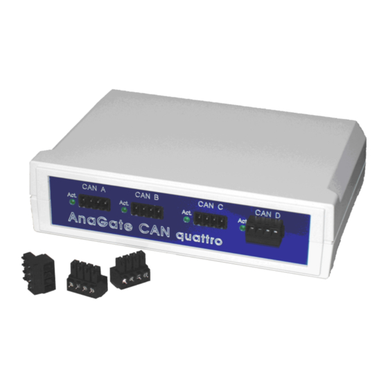
Description 1.4. Interfaces and plugs 1.4.1. AnaGate CAN quattro - front view Figure 1.1. Front view, AnaGate CAN quattro The front panel of the AnaGate CAN Gateway features for each existing CAN interface, the following connectors and LEDs (from left to right): Activity LED This green LED lights up on activity on the relevant CAN line. - Page 10 Description 1.4.2. AnaGate CAN quattro - rear view Figure 1.2. AnaGate CAN quattro, back panel The rear panel of the AnaGate CAN Gateway features the following connectors and LEDs (from left to right): Power LED This green LED lights up when voltage is being supplied.
-
Page 11: Configuration
The PC used for the configuration must be in the 192.168.1.x network. The static IP address 192.168.1.2 with the subnet mask 255.255.255.0 can be e.g. used. If neccessary the settings of the network interface on the configuration pc has to be changed temporarily. © 2007-2010 Analytica GmbH... -
Page 12: Network Settings
Maybe the ARP cache of the PC has to be deleted to find the device with the changed IP address. 2.3. CAN settings On the page CAN Settings the global settings for all existing CAN interfaces are displayed and can be changed individually. © 2007-2010 Analytica GmbH... - Page 13 IP address of the partner device, to which a connection (bridge) is to be made (only Bridge Modus). at Port Port of the partner device, to which a connection (bridge) is to be made (only Bridge Modus). © 2007-2010 Analytica GmbH...
-
Page 14: Functional Extensions Based On Lua
2.4. Functional extensions based on LUA On a AnaGate CAN quattro it is possible to execute self-created applications with an installed LUA script interpreter (see [Prog-2010] for a detailed description of all programming features). On the page LUA LUA script files can be downloaded to the device and executed locally. -
Page 15: Digital Io
At the inputs IN1 to IN4 any external voltage between VCC and GND can be applied. As soon as the voltage difference between INx and GND is more than 1.0 V, the AnaGate CAN Gateway interprets the input as logically HI otherwise LOW. © 2007-2010 Analytica GmbH... -
Page 16: Firmware Update
After pressing shortly the RESET button the device starts to pulse out the current n settings via the yellow activity LED. Pressing again the buttons stops the pulsing immediately. The IP address and subnet mask are pulsed out, one after the other. Following pulse codes are used: © 2007-2010 Analytica GmbH... - Page 17 • Dot: 1x very fast flash Between two single digits a delay of 1 seconds is made, and between the IP address and subnet mask two fast flashes are pulsed out. Figure 2.6. AnaGate CAN Gateway, Example blinking output © 2007-2010 Analytica GmbH...
-
Page 18: Fields Of Application
CAN bus or to create single CAN telegrams. • Application programs, which are using the included software API inteface. • Self-created batch files which are executed via the included LUA interpreter with integrated AnaGate software API. © 2007-2010 Analytica GmbH... -
Page 19: Bridge Mode
• The internal termination resistor is to be set on/off for the CAN port of the parter device. When the AnaGate CAN Gateway establishes the connection to the partner device succesfully, the specified baud rate and integrated termination option is automatically set on the partner device. © 2007-2010 Analytica GmbH... - Page 20 To interconnect the two CAN interface on a single device, the own IP address or 127.0.0.1 has to be used. In this case the specified remote baud rate and termination is used on the interconnected interface. © 2007-2010 Analytica GmbH...
-
Page 21: Faq - Frequent Asked Questions
PC or if there is a packet filter in the network between your PC and the AnaGate. Using a firewall When working with a firewall, the a TCP port has to be opened for communication with the AnaGate device: © 2007-2010 Analytica GmbH... - Page 22 120 Ohm, as required by the CAN bus. Does Analytica offer a CAN gateway which does not have an galvanically isolated CAN interface? Any device that is actively connected to a CAN bus should be galvanically isolated. Especially when using USB-operated devices (like the AnaGate USB), it is essential to have an galvanically isolated device, because the device is power supplied by the PC.
-
Page 23: Technical Support
Analytica GmbH. Technical support can be requested as follows: Internet The AnaGate web site [http://www.anagate.de/en/index.html] of Analytica GmbH contains information and software downloads for AnaGate Library users: • Product updates featuring bug fixes or new features are available here free of charge. -
Page 24: Abbreviations
Abbreviations Controller Area Network CAN in Automation DHCP Dynamic Host Configuration Protocol © 2007-2010 Analytica GmbH... -
Page 25: Bibliography
[NXP-I2C] NXP Semiconductors. Copyright © 2007 NXP Semiconductors. UM10204. I2C-bus specification and user manual. Rev. 03. 19.06.2007. [TCP-2010] Analytica GmbH. Copyright © 2010 Analytica GmbH. Manual TCP-IP communication. Version 1.2.6. 15.05.2008. [Prog-2010] Analytica GmbH. Copyright © 2010 Analytica GmbH. AnaGate API. Programmer's Manual. Version 1.4.
Need help?
Do you have a question about the AnaGate CAN quattro and is the answer not in the manual?
Questions and answers