
Subscribe to Our Youtube Channel
Related Manuals for Microchip Technology CAN Bus Analyzer

Summary of Contents for Microchip Technology CAN Bus Analyzer
- Page 1 CAN Bus Analyzer User’s Guide 2009-2022 Microchip Technology Inc. and its subsidiaries DS50001848D...
- Page 2 Microchip Technology Inc. in other countries. stated. GestIC is a registered trademark of Microchip Technology Germany II GmbH & Co. KG, a subsidiary of Microchip Technology Inc., in other countries. All other trademarks mentioned herein are property of their respective companies.
-
Page 3: Table Of Contents
Chapter 1. Introduction....................9 1.1 Introduction ..................... 9 1.2 Can Bus Analyzer Kit Contents ..............9 1.3 Overview of the CAN Bus Analyzer ..............9 1.4 CAN Bus Analyzer Hardware Features ............10 1.5 CAN Bus Analyzer Software ................ 12 Chapter 2. - Page 4 CAN Bus Analyzer User’s Guide NOTES: 2009-2022 Microchip Technology Inc. and its subsidiaries DS50001848D-page 4...
-
Page 5: Preface
The topics discussed in this preface include: • Chapter 1. “Introduction” • Chapter 2. “Installation” • Chapter 3. “Using the PC GUI” • Appendix A. “Error Messages” 2009-2022 Microchip Technology Inc. and its subsidiaries DS50001848D-page 5... -
Page 6: Conventions Used In This Guide
Choice of mutually exclusive errorlevel {0|1} character: { | } arguments; an OR selection Ellipses... Replaces repeated text var_name [, var_name...] Represents code supplied by void main (void) user { ... 2009-2022 Microchip Technology Inc. and its subsidiaries DS50001848D-page 6... -
Page 7: Recommended Reading
Preface RECOMMENDED READING This user’s guide describes how to use the CAN Bus Analyzer on a CAN network. The following Microchip documents are available on www.microchip.com and are recom- mended as supplemental reference resources to understand CAN (Controller Area Network) more thoroughly. -
Page 8: Customer Support
Software” Section 3.2 “Trace Feature”. • Typographical edits throughout document. Revision C (February 2022) • Updated Section 1.4 “CAN Bus Analyzer Hardware Features ”. Revision D (April 2022) • Updated Section 1.4 “CAN Bus Analyzer Hardware Features ”. • Typographical edits throughout document. -
Page 9: Chapter 1. Introduction
The CAN Bus Analyzer provides similar features available in a high-end CAN network analyzer tool at a fraction of the cost. The CAN Bus Analyzer tool can be used to monitor and debug a CAN network with an easy-to-use Graphical User Interface. The tool allows the user to view and log received and transmitted messages from the CAN Bus. -
Page 10: Can Bus Analyzer Hardware Features
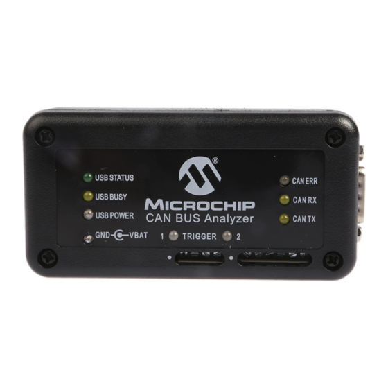
CAN Bus Analyzer User’s Guide CAN BUS ANALYZER HARDWARE FEATURES The CAN Bus Analyzer hardware is a compact tool that includes the following hardware features. Refer to Section 1.5 “CAN Bus Analyzer Software” for more information about the software features. - Page 11 FIGURE 1-2: CAN BUS ANALYZER SCHEMATIC USB Busy Yellow LED Yellow LED LED1 LED1 0.1 μF Green LED Green LED LED2 LED2 RB0/INT0/AN12/FLT0/SDI/SDA MCLR/V /RE3 27 pF RB1/INT1/AN10/SCK/SCL OSC1/CLKIN 9 RB2/AN8/INT2/VMO Not Suspend RB3/AN9/CCP2/VPO Note: np = not populated RB4/AN11/KBI0...
-
Page 12: Can Bus Analyzer Software
CAN Bus Analyzer User’s Guide CAN BUS ANALYZER SOFTWARE The CAN Bus Analyzer comes with two firmware Hex files and PC software which provide the user with a graphical interface to configure the tool, and analyze a CAN network. It has the following software tool features: 1. -
Page 13: Chapter 2. Installation
Hex files are programmed into their respective PIC18F microcontrollers on the CAN Bus Analyzer hardware. 2.2.2 Upgrading the Firmware If upgrading the firmware in the CAN Bus Analyzer, the user will need to import the Hex ® ® files into MBLAB IDE and program the PIC MCUs. -
Page 14: Hardware Installation
Connecting the CAN Bus Analyzer to the PC and CAN Bus 1. Connect the CAN Bus Analyzer via the USB connector to the PC. You will be prompted to install the USB drivers for the tool. The drivers can be found in this... - Page 15 Signal Description ® MCU Power Supply CAN_L Dominant Low CAN_H Dominant High CAN Digital Signal from Transceiver CAN Digital Signal from PIC18F2680 Ground FIGURE 2-2: PINOUT FOR THE SCREW-IN TERMINALS CANL CANH 2009-2022 Microchip Technology Inc. and its subsidiaries DS50001848D...
- Page 16 CAN Bus Analyzer User’s Guide NOTES: 2009-2022 Microchip Technology Inc. and its subsidiaries DS50001848D-page 16...
-
Page 17: Chapter 3. Using The Pc Gui
The following are setup steps to quickly start transmitting and receiving on the CAN Bus. For more details, refer to the individual sections for the different PC GUI features. 1. Connect the CAN Bus Analyzer to the PC with the mini-USB cable. 2. Open the CAN Bus Analyzer PC GUI. -
Page 18: Trace Feature
The Fixed Trace window will show the CAN messages in a fixed position on the Trace window. The message will still be updated, but the time delta between messages will be based on the previous message with the same CAN ID. 2009-2022 Microchip Technology Inc. and its subsidiaries DS50001848D-page 18... -
Page 19: Transmit Feature
2. Populate the Periodic field (50 ms to 5000 ms). 3. Populate the Repeat field (with a value from 1 to 10). 4. Click on the Send button for that row. 2009-2022 Microchip Technology Inc. and its subsidiaries DS50001848D... -
Page 20: Hardware Setup Feature
FIGURE 3-5: HARDWARE SETUP WINDOW The Hardware Setup window allows the user to set up the CAN Bus Analyzer for com- munication on the CAN Bus. This feature also gives the user the ability to quickly test the hardware on the CAN Bus Analyzer. -
Page 21: Appendix A. Error Messages
“0-8”. 4.20.x Enter DATA within the following range Enter valid data into the TEXT field. The tool is expecting a (0-FF) hexidecimal value in the range of “0-FF”. 2009-2022 Microchip Technology Inc. and its subsidiaries DS50001848D-page 21... - Page 22 6.00.x Unable to Log Data Tool is unable to write CAN traffic to Log File. Possible cause may be that the drive is either full, write-protected or does not exist. 2009-2022 Microchip Technology Inc. and its subsidiaries DS50001848D-page 22...
- Page 23 Error Messages NOTES: 2009-2022 Microchip Technology Inc. and its subsidiaries DS50001848D...
-
Page 24: Worldwide Sales And Service
Tel: 46-31-704-60-40 Tel: 631-435-6000 Sweden - Stockholm San Jose, CA Tel: 46-8-5090-4654 Tel: 408-735-9110 UK - Wokingham Tel: 408-436-4270 Tel: 44-118-921-5800 Canada - Toronto Fax: 44-118-921-5820 Tel: 905-695-1980 Fax: 905-695-2078 2009-2022 Microchip Technology Inc. and its subsidiaries DS50001848D-page 24 09/14/21...
Need help?
Do you have a question about the CAN Bus Analyzer and is the answer not in the manual?
Questions and answers