Table of Contents
Advertisement
Quick Links
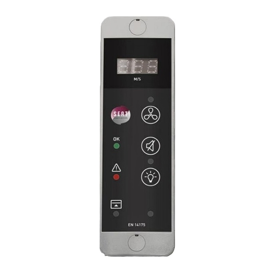
Type A Remote
controller
REF 819750/819751
The remote controller type A is a safety device for monitoring a fixed air flow.
A speed sensor is used to determine the flow rate. An audible and visual alarm is set off in
case of insufficient speed or too high sash height and other malfunctions.
The remote HMI (Human Machine Interface) is used to control the fume cupboard
ventilation and to carry out the necessary adjustments on site.
This controller complies with EN 14175 and RoHS standards.
Advertisement
Table of Contents

Related Manuals for Seat 819750

Summary of Contents for Seat 819750
- Page 1 Type A Remote controller REF 819750/819751 The remote controller type A is a safety device for monitoring a fixed air flow. A speed sensor is used to determine the flow rate. An audible and visual alarm is set off in case of insufficient speed or too high sash height and other malfunctions.
-
Page 2: Table Of Contents
Table of contents Presentation ............................ 3 1.1. HMI (Human Machine Interface) ....................3 1.2. CPU (Central Processor Unit) ....................... 3 1.3. Schematic diagram ........................4 1.4. Connector specifications ......................5 Installation and mounting ....................... 6 2.1. Dimensions ..........................6 2.2. Positioning on the fume food ...................... -
Page 3: Presentation
1. Presentation The remote type A flow controller consists of a small HMI, easily installed on a fume cupboard, and a central processor. 1.1. HMI (Human Machine Interface) Display (Option) Yellow LED: Ventilation ON/OFF Push button: ON/OFF ventilation Green LED: air flow OK Push button: stop buzzer Yellow LED: Lighting ON/OFF Red LED: insufficient air flow... -
Page 4: Schematic Diagram
1.3. Schematic diagram Power contactor Motor power supply Velocity probe Switch sash position Deported HMI CPU box The type A flow controller is used to control the air flow of a fume hood. Pressing the ON/OFF ventilation button on the remote interface closes the two relays VENT 1 and VENT 2, which supplies the fan via a power contactor. -
Page 5: Connector Specifications
1.4. Connector specifications Alimentation Electrical transformer 230v/12v 500mA. (delivered with) VENT1/FAN1 ON/OFF Ventilation relay driving by Disconnection voltage: 120v Disconnection current: 0.5 A VENT2/FAN2 Same VENT1 LIGHT ON/OFF lighting relay driving by Disconnection voltage: 220v Disconnection current: 3 A ALARM Relay controlled by alarm activation. -
Page 6: Installation And Mounting
2. Installation and mounting 2.1. Dimensions 65 mm 28 mm 40 mm 22 mm Speed sensor... -
Page 7: Positioning On The Fume Food
2.2. Positioning on the fume food You can install the CPU The controller is delivered with a 2,5 meters cable. in the false ceiling of the fume cupboard. ◌ Vertical HMI are usually attached to the side frame of fume hoods. Horizontal HMI’s can be set at the user’s convenience. -
Page 8: Cutting Template
2.3. Cutting template If you want to install your fume hood controller without the surface bow mounting, you will need to make the following cuts: 31mm 110mm... -
Page 9: Installation Tips
2.4. Installation tips • Do not install the sensor on the extraction tube above the fume hood • Avoid installing the sensor in a dead zone of the fume cupboard • The probe must pass entirely through the fume cupboard ceiling. Otherwise, you must use a 25mm PVC tube to extend the outlet. -
Page 10: Wiring Diagram
3. Wiring diagram 220v power supply ON/OFF Ventilation Motor power supply Switch sash position... -
Page 11: Adjustment Procedure
4. Adjustment procedure Alarm threshold setting Switch on ventilation with Sash opened Lift up the sash in high position (400mm or 500mm). Wait 15 seconds for the air speed to stabilize. Enter the setting mode: Press for at least 3 seconds on release and press simultaneously on shortly. -
Page 12: Factory Reset
Press the push-button on the electronic board to synchronize the speed reading on the anemometer and the speed displayed on the controller. One push increase by 0.1 m/s over a range of 0.3 to 0.7 m/s. After adjustment, a long press on allows to validate the alarm threshold 0.1 m/s below the speed measured by the controller and to exit the setting mode. -
Page 13: Change The Audible Alarm Delay
7. Change the audible alarm delay It is possible on the rear face to change the buzzer’s trigger time with the two switches. 1 = ON: Alarm still active 1 = OFF: Alarm disabled if ventilation is off 2 = ON: delay set at 30s 2 = OFF: delay set at 15s 8. -
Page 14: Faq
9. FAQ Questions Solutions Check that the power supply is correctly connected. No indicator Check that the controllers ON button is fully engaged and that The fan does not start the yellow light above is on. Check wiring. Check that the speed sensor is correctly connected to the The display shows "PB"... -
Page 15: Maintenance
Have an anemometer 11. Warranty SEAT Ventilation guarantees that its equipment, products and parts are free from manufacturing defects under normal conditions of use for a period of two years after delivery to the first user. If a factory return is required during the two years period from the date of purchase, contact your distributor. - Page 16 SEAT VENTILATION SAS PARC TECHNOLOGIQUE DELTA SUD 09340 VERNIOLLE France E-mail: info@seat-ventilation.com Site Web: www.seat-ventilation.com...
Need help?
Do you have a question about the 819750 and is the answer not in the manual?
Questions and answers