Table of Contents
Advertisement
Quick Links
Advertisement
Table of Contents

Related Manuals for Evi GT-SKR015KBDC-M10

Summary of Contents for Evi GT-SKR015KBDC-M10
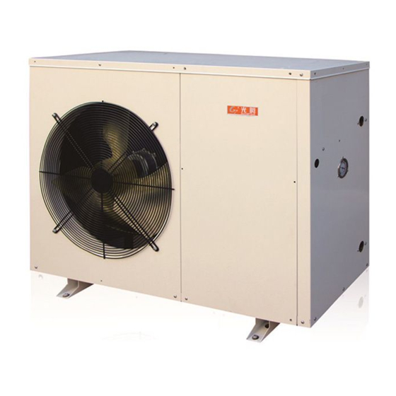
- Page 1 EVI DC Inverter Air Source Heat Pump Instruction Manual Model number: GT-SKR015KBDC-M10 GT-SKR020KBDC-M10 GT-SKR030KBDC-M10 GT-SKR040KBDC-M10 GT-SKR050KBDC-M10 ◆ Please read the manual carefully before installation and maintenance. ◆ Please keep this manual well for future reference.
-
Page 2: Table Of Contents
CONTENTS Part I: General Information ......................... 1 1.1 Caution ............................1 Part II Installation ............................2 2.1 Transportation ..........................2 2.2 Installation site requirement ......................2 2.3 Minimum distance to wall ......................3 2.4 Clearance between outdoor module and ground ................4 2.5 Installation guide .......................... -
Page 3: Part I: General Information
Part I: General Information 1.1 Caution 1. Ensure proper operation on the unit, 2. The unit must be installed and repaired by qualified technician. 3. A leakage protection switch must be installed near the unit. 4. Do not use any damaged cables and switches to avoid any leakage. 5. -
Page 4: Part Ii Installation
Part II Installation 2.1 Transportation Along transportation, don’t incline the unit more than 45°in any direction The unit in its packaging can be transported with a lift truck or hand truck. 2.2 Installation site requirement This unit is designed for outdoor installation, do not install it in an close space. Please consider the condition as following factors when selecting installation site. -
Page 5: Minimum Distance To Wall
2.3 Minimum distance to wall Air discharge Minimum 1000mm to obstacles obstructing the air discharge. Minimum 3000mm to footpaths and patios due to the formation of ice, even when outside temperatures are above 0 ° C - 3 -... -
Page 6: Clearance Between Outdoor Module And Ground
2.4 Clearance between outdoor module and ground The minimum installation height must be 300mm. A canopy must be constructed over the outdoor module in areas with heavy snowfall. 2.5 Installation guide 2.5.1 Installation a. Install 4 pieces shockproof rubber pad under the feet of the unit. b. -
Page 7: Recommended Hydraulic Connection
2.6 Recommended hydraulic connection - 5 -... -
Page 8: Electrical Connection
2.7 Electrical Connection 1. Ensure proper operation of the unit, the unit must be installed and repaired by qualified technician. 2. A leakage protection switch must be installed near the unit. 3. Do not use any damaged cable and switch. 4. -
Page 9: Trial Operation
The Specification of Power Following information is for reference, please subject to the local safety norm. Type GT-SKR015KB GT-SKR020KB GT-SKR030KB GT-SKR040KB GT-SKR050KB DC-M10 DC-M10 DC-M10 DC-M10 DC-M10 Power supply 220-240V/1Ph/ 220-240V/1Ph/ 220-240V/1Ph/ 220-240V/1Ph/ 380-415V/3Ph/ 50Hz 50Hz 50Hz 50Hz 50Hz Circuit Breaker/Fuse(A) Min. -
Page 10: Part Iii Control System
2.8.3 Caution When following happen during trial operation, please stop the unit immediately and cut off the power and contact with our authorized agent or maintenance technician. Fuse blown or protection activated frequently. The wire and switches are heated abnormally ●... -
Page 11: Controller Introduction
3.2 Controller introduction Cooling Water pump Heating E-heater Lock the keys Defrosting Clock Compressor Timer on Timer off 3.3 Operation introduction Lock and unlock buttons 1. In locked status, press button for 5 seconds, the buzzer will sound and unlock the buttons. - Page 12 Standby status Function button 1. In main menu, press button to switch working mode. The units have 5 working modes as below: (1): Heating mode The left side of the screen shows the set water temperature of buffer tank; The right side of the screen shows the measured water temperature of buffer tank.
- Page 13 (3): DHW mode The left side of the screen shows the set DHW water temperature; The right side of the screen shows the measured DHW water temperature. Press to adjust the set DHW water temperature, the maximum DHW water temperature can be set is 55℃. DHW status (4): heating + DHW mode (DHW priority) -When the unit is in heating status,...
- Page 14 temperature of buffer tank, the minimum water temperature can be set is 8℃. -When the unit is in DHW status, flash on the screen, the left side of the screen shows the set DHW water temperature; The right side of the screen shows the measured DHW water temperature.
- Page 15 ℃ 21 Inlet temp of auxiliary circuit -30~105 evaporation temperature in auxiliary circuit ℃ -30~105 22 Outlet temp of auxiliary circuit EVI suction temperature ℃ 23 Exhaust temp -30~140 ℃ -30~105 24 Outdoor coil temperature ℃ 25 Outdoor environment temperature -30~105...
- Page 16 After setting, it needs to be powered off to take effect. 0: off Power lost memory function 1: on Air temperature to start E-heater -30~20 Air temperature to enter EVI 0~10 0: DC 1: single speed 2: double speed Type of fan 3: three speed After setting, it needs to be powered off to take effect.
- Page 17 Water temperature compensation 0: no function 1: yes ℃ Set room temperature 15~25 ℃ Initial BTW temperature 15~25 ℃ Max. BTW temperature 24~50 -30 ~50 Extend defrosting interval 1 -30 ~50 Extend defrosting interval 2 ℃ -30 ~30 Defrosting enter temp 1 ℃...
- Page 18 Max. operating temperature in ℃ 10~60 heating Min. operating temperature in ℃ -35~10 heating Reserved Reserved 1~13 Reserved 1~13 Reserved 1~10 Reserved 1~10 Reserved ℃ Reserved Reserved Quantity of machines work in series Display machine work in series Reserved Reserved Reserved cure 0: off...
- Page 19 Defrosting parameters setting (only for technician operating) 1. In main menu, press button for 3 seconds to enter parameter setting menu, press button to set parameters. Press button to save setting. 2. In parameter setting menu, if there is no operation for 30 seconds, will automatically exit parameter setting and back to main menu.
- Page 20 1. Press buttons simultaneously to enter / exit ECO mode, display on the screen. The heating curve parameters setting (only for technician operation) a. In main menu, press button for 3 seconds to enter parameter setting menu, press button to set parameters. Press button to save setting.
- Page 21 b. When outside temp=0° C, Target buffer tank temp = 20+(43-20)/35x(25-0)=36° C c. When outside temp=-15° C, Target buffer tank temp = 20+(43-20)/35x(25+15)=46° C 2. When Air temperature sensor failure, in OFF status, in DHW mode, and in cooling mode, the unit doesn’t run according to heating curve.
- Page 22 5. After the timer OFF is set, press button again to save timer 1 ON and OFF setting. And enter timer ON and OFF setting of timer 2. The setting is same as setting of timer 1. 6. In timer setting menu, press button to cancel the current setting of timer ON/OFF.
- Page 23 Wi-Fi control Scan the QR code to install the APP of “Smart Life”, after installing the APP, the software will display on you mobile phone. 1. Software registration Ensure the unit and mobile phone connected to a Wi-Fi. Please complete registration step by step if new user. After registration is complete, please log in to the software by user name and password you have set, the heat pump and mobile phone should be connected to WIFI.
- Page 24 3. Connect the heat pump Option 1: On controller of heat pump, press simultaneously, to enter Smartconfig mode, blink quickly on the screen. On the App, choose Blick Quickly - 22 -...
- Page 25 Option 2: On controller of heat pump, press simultaneously, to enter AP mode, blink slowly on the screen. On the App, choose Blick Slowly 4. Add device After connecting to the heat pump by AAP, the unit can be turned on/off by APP, can be set water temperature by APP, can be choose working mode by APP, can set timer by APP.
- Page 26 : Turn on/off the unit : Set working mode : Set clock Dry contact The dry contact should be short-circuited when not in use. Otherwise the controller will fail in heating/cooling mode. When the dry contact is connected to a thermostat, in heating/cooling mode, the unit will stop or startup according to the signal of the thermostat.
- Page 27 Anti-legionella function 1. When connect the E-heater in DHW water tank to the Anti-legionella signal port, installing an AC contactor is required. Otherwise it will burn out the PCB. 2. The anti-legionella parameters setting (only for technician operating) a. In main menu, press button for 3 seconds to enter parameter setting menu, press button to set parameters.
- Page 28 Work in series function Multiple machines can be run jointly with work in series function. The master unit controls all slave units. 1. Take the controller (of all machines) out from port CN16 on PCB. Connect signal wire to CN16. 2.
- Page 29 4. After wiring connection, set the quantity of machines work in series by controller. In main menu, press button for 3 seconds till there is a beep. Enter parameter b55 by pressing , press button, press to set quantity of machines work in series.
-
Page 30: Part Iv Maintenance
Part IV Maintenance Before performing any maintenance on the unit, you should turn the unit off first and shut off the power. A well-maintained heat pump could save your energy costs and make the unit durable, but must be done by a qualified technician. Below are some tips for your reference to help your heat pump gives you optimum performance. -
Page 31: Part V Trouble Shooting
Part V Trouble Shooting Type Code Description Remark 1. The signal line between PCB and driver board is Communication open circuit, short circuit or wrong line sequence. Repair failure between PCB or replace the signal line. and driver board 2. The PCB is damaged. Replace it. 3. - Page 32 Exhaust temp sensor 2. The sensor is damaged. Replace it. failure 3. The PCB is damaged. Replace it. EVI return circuit air 1. The sensor isn’t connected well. Reconnect it. return temp sensor 2. The sensor is damaged. Replace it.
- Page 33 1. Insufficient water flow: a. The water piping is blocked. Check the water piping and clean the Y-type filter. b. There is air in the water piping. Vacuumize it. c. The power of circulation pump is insufficient. Change High pressure switch to a larger one.
- Page 34 d. The circulating pump is damaged. Repair or replace 2. The temperature sensor falls off or is damaged. Re-fix or replace the temperature sensor. 1. Check if the refrigerant is sufficient. Check for Overheat protection leakage, and replenish refrigerant. of compressor 2.
- Page 35 1. Ambient temperature is lower than 0℃ when cooling. Environment temp is 2. The ambient temperature sensor is damaged. too low in cooling Replace it. 3. The PCB is damaged. Replace it. The possible causes and treatment of common failure. Fault Condition Possible Causes Treatment...
- Page 36 ◇Liquid refrigerant goes into ◇Check the expansion valve ◇Replace the compressor the compressor The compressor ◇interior components works but too ◇Add in adequate refrigeration oil noisy destroyed ◇Inadequate refrigeration oil ◇Capacitor damaged ◇Replace it ◇The fans are not fixed well ◇Fix it well again The fan doesn’t ◇The electromotor burned...
-
Page 37: Part Vi Wiring Diagram
Part VI Wiring Diagram GT-SKR015KBDC-M10, GT-SKR020KBDC-M10, GT-SKR030KBDC-M10 - 35 -... - Page 38 GT-SKR040KBDC-M10 - 36 -...
- Page 39 GT-SKR050KBDC-M10 - 37 -...
-
Page 40: Disposal
Disposal Do not dispose this product as unsorted municipal waste. Collection of such waste separately for special treatment is necessary. Do not dispose of electrical appliances as unsorted municipal waste, use separate collection facilities. Contact your local government for information regarding the collection systems available. If electrical appliances are disposed of in landfills or dumps, hazardous substances can leak into the groundwater and get into the food chain, damaging you health and well-being.
Need help?
Do you have a question about the GT-SKR015KBDC-M10 and is the answer not in the manual?
Questions and answers