
Related Manuals for Evi FA-03EVI

Summary of Contents for Evi FA-03EVI
- Page 1 EVI air source heat pump User Manual FA-03EVI Please properly keep this manual. Please read this manual carefully before using the machine.
- Page 3 N ot e Content 1.Safe precautions 2.Structure 3.Installation 4.Electric connection 5.User instruction 6.Trial operation 7.Unit operation and performance 8.Maintenance and trouble shooting 9.Wiring diagram...
- Page 4 CN7 CN6 1 2 3 4 1 2 3 4 W_COM AC380V A1 main control board KM1 comp AC contactor A2 wire controller H1 electrical heater for defrost A3 phase sequence protection R1 hot water tank sensor A4 current transformer R2 outlet water sensor M1 compressor R3 coil sensor...
- Page 5 8.Maintenance and trouble shooting 1.Safety Precautions ! Warning 8-2 Malfunctions and treatment ! Requirements for the installation environment Warning The installation location must be ventilated, waterproof, sun-proof, and requires a convenient power If any fault occurs and the unit stops running, please contact your dealer or after-sales technician to supply, water supply and drainage channels.
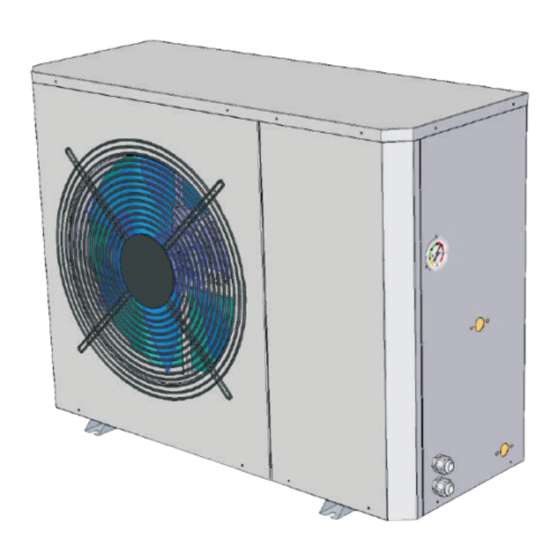
- Page 6 2.Structure 8.Maintenance and trouble shooting 2-1 Outer Structure 8-1 Fault code table 425mm 1105mm The unit will stop automatically if any fault happens during the operation, meanwhile, the fault code will display on the controller screen. Please contact the serviceman to check by referring to the flowing table and exclude the fault.
- Page 7 2.Componenents name 7.Unit operation and performance 2- 2 The main components name 1-Axial fan blade 5-High pressure switch 9-Heat exchanger 2-Axialfan motor 6-Compressor 10-4 way valve 3-Economizer 7-Water flow switch 11-Check valve 4-Expansion valve 8-Electric box 12-Gas-liquid seperator...
- Page 8 3.Installation 7.Unit operation and performance ! 7-1 explanation for some phenomena during the unit operation Attention 1)Start delay; During the unit running, if the unit is turned off or stops automatically, if restart the unit, the The following installation places may cause the malfunction of the machine unit has to wait for 3 minutes to start.
- Page 9 6.Trial operation 3.Installation 3-2 Movement 6-1 Inspection before the trial operation 1)Because the gravity center of the unit is not in the middle, when you move the machine, please beware of the drumping. Please check if the following items before the trial operation. 2) Please do not hold the air inlet, or it will be deformed.
- Page 10 3.Installation 5.User instruction Energy saving mode 3-4 The space of installation and maintenance When you choose the “energy-saving mode”, the unit can adjust the Please leave enough maintenance space as the below water inlet temperature intelligently according to the ambient before the installation.
- Page 11 5.User instruction 3.Installation 3-5 Installation of the water pipes TIMING ON: 20:10 TIMING ON: 20:10 TIMING OFF: 00:00 1)To reduce the resistance of the water pipe as much as possible , reducing the elbow TIMING OFF: 06:30 position and variable diameter can be adopted. 2) In the process of the piping connection, please make sure the whole system to be clean, no rust and no other dirt, in order to prevent the piping blockage.
- Page 12 3.Installation 5.User instruction 8)Timer setting 3-7 Antifreezing measures In the main menu, press “ Prg ” to enter into the parameter page, then press “ ” to select the “timer setting”; 1) When the ambient is lower than minus 5℃, please make sure the unit is energized. Press the “...
- Page 13 5.User instruction 3.Installation 3-8 Installation diagram A.C.△T Statu 5℃ a. Installation for only heating Heating SET 41℃ Parameter Cooling SET 12℃ Time Setting AC Auto SET 40℃ buffer tank Timer Setting DHW △T 5℃ DHW SET 50℃ floor heating circulation pump Heating type curve Translation set...
- Page 14 5.User instruction 3.Installation 6)Parameter setting c. Installation for hot water & heating hot water tank In the main menu, press “ Prg ” to enter into the parameter page, the “Statu” will light the white line; Press the “ ” to make the “Parameter” become white line; Press the “...
- Page 15 5.User instruction 4.Electric connection Parameter Parameter meaning Setting range Default 4-1 Electric wiring A.C. ΔT Delta temp. of the heating set 2~18℃ 5℃ Heating set Set temp. of the heating mode 20~55℃ 40℃ ! Attention Cooling set Set temp. of the cooling mode 8~30℃...
- Page 16 2. Connect with water pump fan motor statu 3. Connect with 3-way valve 4way valve 4-way valve statu EVI valve EVI valve statu unloader no use Through the power line from the hole, and connect the line with the 3way-valve 3-way valve statu terminal.
- Page 17 5.User instruction 5.User instruction 5)Parameter query 5-1 Controller description In the main menu, press “ Prg ” to enter into the parameter page, the “Statu” will light the white line; Press the “ ” to enter into the number page; Press the “...
- Page 18 5.User instruction 5.User instruction 4)Temperature adjustment setting 5-2 Operation instruction 1)Initialization In the main menu, press the “ ” or “ ”, the hot tank temp. parameter will flash; After the unit is energized, the controller’s back light will light and the initialization page will show.
Need help?
Do you have a question about the FA-03EVI and is the answer not in the manual?
Questions and answers