Advertisement
Technical Note
Inertia-Link
3DM-GX2
Orientation Sensors
Overview
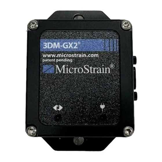
MicroStrain's Inertia-Link
interface. There is no standard for connector pin compatibility between RS-422 devices made by
different vendors. This technical note presents an example of how the Inertia-Link
®
GX2
can be interfaced to another vendor's device.
Pin Assignments
®
The Inertia-Link
and 3DM-GX2
the enclosure. This connector provides the communications and power interface to the devices.
The pin layout as viewed from outside the enclosure is shown in the following figure:
The connector pin assignments are described in the following table and notes:
®
®
®
®
and 3DM-GX2
can be outfitted with an RS-422 communications
®
present a female Micro-D 9-pin connector on the sidewall of
Figure 1
Pin #
RS422
1
-
2
-
3
+5V
4
RxD+
5
RxD-
6
+6V/+9V/+12V
7
TxD+
8
GND
9
TxD-
Table 1
1
2
2
1
2
2
®
and 3DM-
Advertisement
Table of Contents

Summary of Contents for MicroStrain Inertia-Link 3DM-GX2
- Page 1 Orientation Sensors Interfacing with Other RS-422 Devices Overview ® ® MicroStrain’s Inertia-Link and 3DM-GX2 can be outfitted with an RS-422 communications interface. There is no standard for connector pin compatibility between RS-422 devices made by ® different vendors. This technical note presents an example of how the Inertia-Link and 3DM- ®...
- Page 2 ® ® does not provide power to the Inertia-Link and 3DM-GX2 ; power must be provided through the standard MicroStrain cable or through user-designed means. MicroStrain, Inc. 310 Hurricane Lane, Unit 4 ph: 800-449-3878 Williston, VT 05495 USA fax: 802-863-4093 Copyright ©...

Need help?
Do you have a question about the Inertia-Link 3DM-GX2 and is the answer not in the manual?
Questions and answers