
Subscribe to Our Youtube Channel
Related Manuals for Thermaltake Tai-Chi VB5001SNA


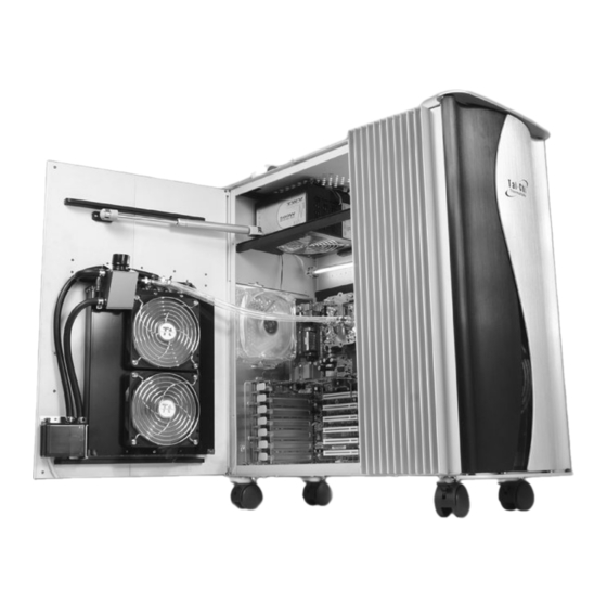
Summary of Contents for Thermaltake Tai-Chi VB5001SNA
- Page 1 VB5001SNA User Manual C 2005 Thermaltake Technology Co.,Ltd. All Rights Reserved. www.thermaltake.com...
-
Page 2: Table Of Contents
Contents Chapter1 Product Introduction 1.1 Specification Chapter2 Case Mechanical Operation 2.1 How to open the side panel 2.2 Installing 5.25" Device 2.3 Installing 3.5" HDD 2.4 Installing 3.5" Device to Drive Tray With Power Button 2.5 How to Remove the Fan & Fan Holder 2.6 BTX Upgraded Kits 2.7 PCI slot tool-free function operation Chapter3 Motherboard &... -
Page 3: Chapter1 Product Introduction
Chapter1 Product Introduction Chapter2 Case Mechanical Operation 1.1 Specification 2.1 How to open the side panel V B 5 0 0 1 S N A Remove two screws on the right Model Tai-Chi --- VB5001SNA (with liquid cooling system) side of the side panel displayed Case Type Liquid Cooling System Case in the picture. -
Page 4: Installing 5.25" Device
2.3 Installing 3.5" HDD 2.2 Installing 5.25" Device ( For 12cm Fan Cage ) Remove thumb screws at both side and remove the fan cage Remove the drive bay cover from the selected position, then insert the device into the 5.25" drive bay Insert HDD by sliding HDD into the 12 cm fan cage. -
Page 5: Installing 3.5" Device To Drive Tray With Power Button
2.4 Installing 3.5" Device to Drive Tray With Power Button Remove and slide drive bay out-ward to remove. Place cover back to drive tray to its original position. Insert 3.5" device and secure device with screw. Insert the device tray pictured above and secure the device tray by thumb screws. -
Page 6: How To Remove The Fan & Fan Holder
2.6 BTX Upgraded Kits 2.5 How to remove the fan & fan holder 12 cm rear fan Push fan clip upward to loose fan, then remove fan holder from inside BTX rear plate BTX SRM (Supported Retention Module) BTX upgraded kit box... -
Page 7: Pci Slot Tool-Free Function Operation
Chapter3 Motherboard & Leads Installation 2.7 PCI slot tool-free function operation 3.1 Motherboard Installation Open the plastic clip then take off the PCI bracket as follow. Each motherboard has different standoff layout. It is highly suggested that you refer to your motherboard's manual when installing motherboard into the case. -
Page 8: Case Led Connections
3.2 Case LED connections 3.3 USB2.0 & IEEE1394 Firewire connection USB connection On the front of the case, you can find some LEDs and switch leads Please consult your motherboard manual to find (POWER SW*1, POWER LED*1, H.D.D. LED*1, RESET SW*1). out the section of "USB connection". -
Page 9: Ear & Mic Connections
3.4 Ear & MIC connections IEEE1394 Firewire connection Please consult your motherboard manual to find out Please consult your motherboard manual to find the section of "front panel audio connector". out the section of "IEEE1394 Firewire connection". IEEE1394a AUDIO TPA+ MIC IN Brank) Brank... -
Page 10: Chapter4 Power Supply
AC Input cycled on/off under high temperature condition. Furthermore, it has been approved by UL, CSA, TUV, VDE, NODIC, CB, FCC, CE, CNS. There are three main products of Thermaltake PSU, it is divided into standard, VR and specialty power supply unit. Please refer to http://www.thermaltake.com/purepower/main.htm... -
Page 11: Liquid Cooling Installation Flow Chart
5.2 Install waterblock 5.2.1 Install the WaterBlock on CPU(AMD K7) 5.1 Liquid Cooling Installation Flow Chart In order to ensure convenience and safety, following the Clip for K7 installation procedure below is strongly recommended. 1.Install Waterblock K7 CPU P.18 K8 CPU P.19 >>... -
Page 12: Clip The Waterblock On Cpu(Amd K8)
5.2.2 Clip the WaterBlock on CPU(AMD K8) Install for K8 Insert the screws through the holes as shown above. Insert the washers and copper columns Turn to the front side then tighten the nut as shown. of motherboard. Remove the retention module and back plate from motherboard first. -
Page 13: Install The Waterblock On Cpu(P4)
5.2.3 Install the WaterBlock on CPU(P4) Clip for P4 Insert the screws through the holes as shown above. Turn to the front side Insert the washers and copper columns Of motherboard. then tighten the nuts as shown. Remove the retention module from bracket motherboard first. Apply a thin layer of thermal compound on the processor. -
Page 14: Install The Waterblock On Cpu(Lga775)
5.2.4 Install the WaterBlock on CPU(LGA775) Clip for P4LGA775 Insert the screws through the holes as shown. Insert the washers and copper columns Turn to the front side of the motherboard. then tighten the nuts as shown. Turn to the back side of motherboard and align the "H" insulator to the 4 holes indicated. -
Page 15: Install Watertube
5.3 Install watertube 1. Please measure and cut 2 tubes for connecting water-block and radiator, its length is around 40 cm. (shown as fig1) 2. Insert one end the tube through the nut, plug the tubes in both inlet and outlet, then tighten the nuts. (shown as fig 2, 3, 4) 3. -
Page 16: Fill Coolant
5.4 Fill Coolant 5. Close the pump.Installation complete. 1. Fill the tank up with coolant. Note: 1.Please make sure there is no air inside the tube when you first time power on the system. 2.If there are bubbles within the tube when operating. You may tap the tubes a few times to remove the bubbles.
Need help?
Do you have a question about the Tai-Chi VB5001SNA and is the answer not in the manual?
Questions and answers