Table of Contents
Advertisement
Quick Links
Advertisement
Table of Contents

Related Manuals for FM Systems IPX


Summary of Contents for FM Systems IPX
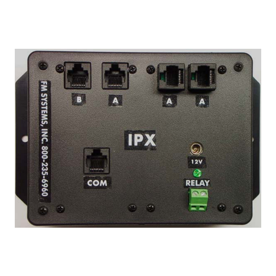
- Page 1 AUTOMATIC IP NETWORK LOSS BACKUP A/B SWITCH INSTRUCTION BOOK IB6444-02...
- Page 2 TABLE OF CONTENTS DESCRIPTION MOUNTING INSTRUCTIONS HOW TO CABLE THE IPX POWER SUPPLY INSTALLATION OPERATION CARE AND MAINTENANCE APPLICATIONS (WHERE TO USE THE SYSTEM) GROUND LOOPS THAT CAUSE INTERMITTANT DATA PROGRAMMING THE RELAY OUTPUT IPXisb PAGE 1 OF 4...
- Page 3 P.O.E is disconnected on the failed data path. Use this unit in any network installation that requires guaranteed continuous communication. The IPX has an easy mounting flange that will mount to any surface with just two screws and is supplied with a 12 VDC power cube.
- Page 4 “A” network then the network will stop transmitting data and go into a polling mode. This failure of the network will be detected by the IPX unit and will output an alarm condition on the relay but the LED will slowly flash on and off indicating a loss of data communication on the primary network.
- Page 5 PROGRAMMING THE RELAY OUTPUT The relay output can be programmed in the field using the jumper jacks on the PC board. The units are shipped from the factory programmed for (NO) Normally Open contacts. If (NC) Normally Closed contacts are desired follow the steps below. Remove the four black screws in the outer most corners of the top lid of the product enclosure.
Need help?
Do you have a question about the IPX and is the answer not in the manual?
Questions and answers