
Related Manuals for Sofraser MIVI


Summary of Contents for Sofraser MIVI
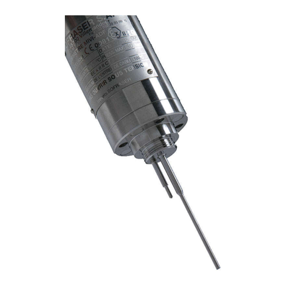
- Page 1 MIVI Technical Manual Process tuning rod probe for viscosity, density and temperature measurements Original version REF.: 379/4...
- Page 2 TO STRICT OBSERVANCE OF INSTRUCTIONS. 2° THE OFFSET ADJUSTMENT IN THE AIR MUST BE THE FIRST TASK COMPLETED WHEN THE MIVI IS INSTALLED ON ITS MOUTING. Clean and dry the vibrating rod of the viscometer in order to make it neat and dry;...
-
Page 3: Table Of Contents
Checking the equipment when placed in the process line ....17 Offset adjustment in air ..................17 Refence point ......................17 OPERATION AND CALIBRATION....................18 MIVI utilization ...................... 18 Periodic checking ....................18 3.2.1 Modification of the previous calibration ..........18... - Page 4 APPENDIX A: SPECIFIC CONDITIONS OF USE FOR ATEX MIVI-ADF ..........22 APPENDIX B: SPECIFIC CONDITIONS OF USE FOR IECEX MIVI-ADF ........... 23 APPENDIX C: SPECIFIC CONDITIONS OF USE FOR ATEX AND IECEX MIVI-SI ......24 ANNEX D - LIST OF OTHER SOFRASER DOCUMENTS ..............26...
-
Page 5: General Presentation
A choice of electronic from simple transducer to touchscreen PLC/HMI provides process infor- mation (viscosity, density or temperature) through different kinds of output. Various models The MIVI sensor can be assembled in many different ways to match with the process needed pa- rameters. Here are the main designs: general standard sensor;... -
Page 6: Cable Wires Allocation
1.4.1 European Pressure Equipment Directive and EMC directive Up to 60 bars, MIVI sensors are in accordance to the article 4.3 of the PED 2014/68/UE. In case of higher pressure, sensors are agreed one by one. The mounting flange is an accessory to be welded on the process line. It means it cannot be indi- vidually certified but has to be certified with the whole process line. -
Page 7: Fm Flameproof Enclosure Certification
MIVI Technical Manual 1.4.3 FM flameproof enclosure certification MIVI FM sensors are in agreement with FMRC-3615 class (FM) for equipment installed in explosive gas atmospheres: MIVI FM Class I, Div. 1, Groups A, B, C & D ambient temp. range: from -20°C to 100°C For FM sensors, it is necessary to add a protection in accordance to the area’s risks level. -
Page 8: Atex And Iec Ex Intrinsic Safety Certification
II 1G Ex ia IIC T6 to T1 Ga (*) Tamb(*) see tables APPENDIX C MIVI sensors are in agreement with ATEX directive 2014/34/EU and the associated standards EN 60079-0 (2012) / A11 (2013), EN 60079-11 (2012), but also with the IEC 60079-0:Ed6.0 (2011) and the IEC 60079-11:Ed6.0 (2011). -
Page 9: Installation In Hazardous Area
MIVI Technical Manual 1.4.5 Installation in hazardous area Here are the possible ways to install the MIVI sensors in a hazardous area. HAZARDOUS AREA SAFE AREA Ex d : zone 1 or zone 2 Standard installation for a MIVI-ADF linked to a transducer... -
Page 10: Other Certifications
CRN n° 0F16467.2 by Absa, for the Al- berta province (MAWP 6895kpa, design temperature 300°C, MDMT -200°C). MIVI sensor with “sanitary” design is still manufactured according to the original file and 3A certificate N° 1013 dated March 30 , 1999. -
Page 11: Installation
MIVI Technical Manual 2. Installation Checking the equipment after receipt First and foremost, check the conformity with the ordered equipment. Mainly check if all the parts needed to mount the equipment are delivered. The parts that are intended to be mounted on the process shall be given to the concerned department, for the installation preparation. -
Page 12: Various Mountings And Models
MIVI Technical Manual 2.2.1 Various mountings and models standard pressure high pressure standard design Ø 60 Ø 99 Ø 76 mounting flange 1 O-ring sanitary standard pressure sanitary high pressure sanitary design Ø 70 mounting flange 3 O-rings high pressure... -
Page 13: Plane Side Mounting
For some applications and operating conditions it may be advised to install the MIVI without its flow damper. In this case the flow damper must be replaced by the replacement ring that is delivered with most of the mounting flanges. -
Page 14: Practical Advices
(see technical leaflets ref. 320, 328 or 329), that has the same dimen- sions than the flow damper base, must be placed on the head of the MIVI sensor in order to maintain the O-ring(s) and ensure tightness. -
Page 15: Fluid Homogeneity
PTFE, ADLC and enamel coatings as well as special alloys and electropolish finishing are available. For information the sheath of the standard cable of the MIVI sensor is in PVC material and its cable gland is in chrome-plated brass. - Page 16 The minimal bending radius at the flexible pipe (electric outlet) is of 100 mm. A shorter radius can crush the turns, initiate cracks, generate leakage inside of the MIVI, then fail- ure. Don’t knock, pinch, crush, twist or bend the cable. Its minimum bending radius is 100 mm.
-
Page 17: Mounting Screws Torque
(8 for the high pressure design), or 42 N.m 1 at the M10 screws (8 for the very high pressure design). 2.3.10 Grounding and wiring The MIVI sensor and the electronic devices must be connected to a good earth ground at same voltage level. Use the screw dedicated to the grounding that is implemented on the MIVI sensor. -
Page 18: Operation And Calibration
/ correction feature of the electronics. Third method is to control the response by using the on lab stand method described in SOFRASER technical procedure (Ref.: 307-308) and Newtonian mineral type oils (see APPENDIX D). -
Page 19: Maintenance
Remove the MIVI from its mounting accessory. Take care and warrant the absence of pressure, hazardous chemicals, excessive temperature…, before releasing the mounting screws. Check that MIVI has been installed with its flow damper. If not and in case of doubt take much care REF: 379/4... - Page 20 See chapter 3.2.1 viscometer (see chapter since last check or accepta- 3.2) ble shift. Clean and dry the inside of your mounting accessory before installing the MIVI back on your pro- cess and setting the offset in the air. REF: 379/4...
-
Page 21: Trouble Shooting
MIVI sensor is design for 24/7 utilization and can be used during years and even decades. At its end of life MIVI sensor can be dismantled and each part can be recycled. SOFRASER advises to send the equipment back to its workshop. SOFRASER will dismantle the sensor and reuse or send the parts to the relevant recycling channels. -
Page 22: Appendix A: Specific Conditions Of Use For Atex Mivi-Adf
Sensor part = vibrating rod (ambient temperature must remain within the range “0 °C < T amb. > 190 °C” Main body = body of the MIVI sensor (ambient temperature must within the range “0 °C < T amb. > 190 °C”... -
Page 23: Appendix B: Specific Conditions Of Use For Iecex Mivi-Adf
MIVI Technical Manual Appendix B: SPECIFIC CONDITIONS OF USE FOR IECEX MIVI-ADF Ambient temperature for gas atmosphere: Ambient temperature depending of the different parts of this apparatus Entry of enclosure (without Temperature class Main body and sensor part Entry of enclosure (with pipe) pipe) -20°C ≤... -
Page 24: Appendix C: Specific Conditions Of Use For Atex And Iecex Mivi-Si
MIVI Technical Manual Appendix C: SPECIFIC CONDITIONS OF USE FOR ATEX AND IECEX MIVI-SI Intrinsically Safe installation Other specific conditions: The equipment can be only connected to intrinsically safe certified associate equipment. These combinations must be compatible as regards with the intrinsic safety rules (see electrical parameters). - Page 25 MIVI Technical Manual EXAMPLE of wiring with a 9200 transmitter REF: 379/4...
-
Page 26: Annex D - List Of Other Sofraser Documents
Manual ref. 380 – 9200 transmitter Manual ref. 380 – 9000 transducer Manual ref. 390 – 9510 processor Manual ref. 396 – 9710 processor Contact your distributor or Sofraser with the serial number of your viscometer for relevant ver- sions of the document. REF: 379/4...
Need help?
Do you have a question about the MIVI and is the answer not in the manual?
Questions and answers