Table of Contents
Advertisement
Quick Links
Advertisement
Table of Contents

Related Manuals for Sofraser MIVI 8001


Summary of Contents for Sofraser MIVI 8001
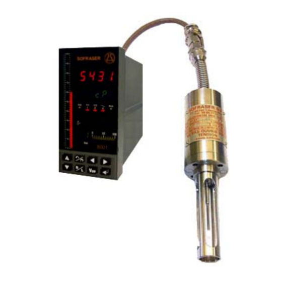
- Page 1 MIVI 8001 Manuel Technique Technical Manual Quality system certified...
- Page 2 Technical Manual MIVI 8001 IMPORTANT BEFORE STARTING THE PROCESS, PROCEED TO THE OFFSET IN AIR ADJUSTMENT. IT MEANS THAT THE ROUGH SIGNAL WILL SHIFTED TO THE REFERENCE "900" : CLEAN AND DRY THE SENSOR ROD. 2. BE SURE THE PROCESS IS EMPTY.
-
Page 3: Table Of Contents
Technical Manual MIVI 8001 TABLE OF CONTENT GENERAL PRESENTATION ................... 5 1.1. The sensor ........................ 5 1.2. The processor......................5 1.3. Checking the equipment at the receipt ..............6 1.4. Checking the equipment when placed at the process ..........6 1.5. - Page 4 Technical Manual MIVI 8001 6.1. Access to the configuration ..................24 6.2. Configuration type "TYPE"..................24 6.3. Inputs N° 1 to 6 "Entr.n"................... 25 6.4. Software alarm N° 1 to 4 "ALRM.n" ................. 25 6.5. Relays outputs 1 and 2 "REL.n" ................25 6.6.
-
Page 5: General Presentation
Technical Manual MIVI 8001 1. General presentation 1.1. The sensor Each sensor is matched with its own electronics. Before switching on, be sure that serial numbers at the sensor and the electronics identification plates are corresponding. The operation principle of the equipment makes that the provided viscosity information is relative: in the same fluid, at the same conditions the information is the same. -
Page 6: Checking The Equipment At The Receipt
Technical Manual MIVI 8001 1.3. Checking the equipment at the receipt a- At first, check the supply conformity with the ordered equipment, mainly the presence of the parts necessary for the equipment mounting. Those to be used at the process will be given to the concerned department, for the installation preparation. -
Page 7: Modification Of The Previous Calibration
Technical Manual MIVI 8001 1.5.2. Modification of the previous calibration The device has been programmed in order to answer to your needs. These features programming steps are noticed on the features specification pages at the end of this document. At first, be sure that the modification is necessary, and not consecutive of a non coherent comparative information (different measuring conditions, bad standards, inaccurate or wrong laboratory measurements,…). -
Page 8: European Pressure Equipment Directive
1.6.4. EMC and low voltage directive MIVI 8001 is in agreement with EMC specifications detailed into 89/336/EEC (modified by 92/31/EEC and 93/68/EEC). 8001 processor is also in agreement with the low voltage directive 73/23/EEC (modified by 93/68/EEC). -
Page 9: The Mivi Sensor
Technical Manual MIVI 8001 2. The MIVI sensor 2.1. Various models General purpose sensors • Sanitary sensors (special design for no retention areas). • Ex-proof sensors (ATEX, FM or JIS approvals). • High-pressure sensors up to 150 bars (reinforced fitting). -
Page 10: Elbow Mounting
Technical Manual MIVI 8001 2.2.1. Elbow mounting The flange is welded on a right angle tee as indicated in fig.1. • The minimal pipe diameter is of 32 mm. Mounting flange, • The flange and the pipe axes have to be superjacent. -
Page 11: Checking
Technical Manual MIVI 8001 WARNING ! In this case, the mounting / removing of the sensor must be made with precaution, in order to avoid to bend the vibrating rod. A ring, with the same dimensions of the protector’s base must be placed on the head of the sensor in order to maintain the O-ring. - Page 12 Technical Manual MIVI 8001 General purpose sensors Exproof sensors Sensor socket (female) Cable plug Earth terminal (male) Earth terminal 1 2 3 4 5 6 7 Cable Screen Cable Pick up coil Pick up Screen coil Motor coil Motor coil...
-
Page 13: Models And Dimensions
Technical Manual MIVI 8001 2.6. Models and dimensions GENERAL PURPOSE HIGH PRESSURE HP ex-proof 200°C Ex-proof 200°C Std 200°C HP 200°C Guard tube long slits 30 mm Guard tube short slits Pot ¼ gas Pot ¼ gas Low pressure High pressure ∅... -
Page 14: Tightness
Technical Manual MIVI 8001 2.7. Tightness ∅ 70 or 99 ∅ 76 or 99 : Gasket ∅ 21.95 × 1.78 : Gasket ∅ 30.00 × 2.00 : Gasket ∅ 29.82×1.78 : Gasket ∅ 30.00 × 2.50 Material : Viton, PTFE, EPDM, Silicone, etc. … on request. -
Page 15: The Processor
Technical Manual MIVI 8001 3. The processor 3.1. Mechanical characteristics Dimensions : 72 x 144 x 203 mm behind the collar. Cut-out : 68 x 138 mm. Weight : 1,8 Kg environ. Metallic casing. Removable drawer. Protection IP 54 on front panel. IP20 on rear panel. -
Page 16: Universal Analog Inputs
Technical Manual MIVI 8001 3.4. Universal analog inputs They are all referenced to the same potential and isolated at 500 Veff from all the other signals. Temperature Sensor Pt 100 Ω -50 à 300°C = 20 Ω max, 0,5.10 3-wire mode /Ω... -
Page 17: Watchdog
Technical Manual MIVI 8001 3.9. Watchdog The device owns a system that controls the functioning of the microprocessor board. When it is wrong, the corresponding output is de-energized (contact opening) and the “watchdog” light on the front panel is on. When everything is OK, this output is energized (the contact is present). -
Page 18: Connections
Technical Manual MIVI 8001 3.11. Connections Inputs wiring Pt100 ohms REL.8 SLOT 3 REL.8 U < 5V Optional current REL.7 REL.7 output (temperature) Volt , mV RS485 2/4 wires 2 wires wiring : Connect Tx+ to Rx+ Connect Tx- to Rx- 0.1%... - Page 19 Technical Manual MIVI 8001 RS422/485 Wiring BUS RS485 3 WIRES MASTER 5K 5K LAST FIRST SLAVE SLAVE Tx+ Tx- Tx+ Tx- 0V Tx+ Tx- 0V shielded cable shielded cable Equipotential connection BUS RS485 5 WIRES MASTER FIRST LAST SLAVE SLAVE...
-
Page 20: General Information
Technical Manual MIVI 8001 Connection advises : The casing earth and the neighbor grounds must be connected between each other through short links and strong sections (big cables). To secure a good on site equi-potentiality, you have to multiply the interconnections (ground meshing). -
Page 21: Material Configuration
Technical Manual MIVI 8001 4. Material configuration When turning on the device, the controller checks all its options and displays its material configuration. SOFRASER Software version Slot1= unused Option board Recognition Slot2= unused code Slot3= unused WITHOUT Slot4= 0/4..20 mA output... -
Page 22: User Mode
Technical Manual MIVI 8001 5. User Mode The USER mode accepts up to two display views (VUE). These views can display the measurements (red display) and the physical units or parameter (green display). The units can be adjusted in User mode by pressing simultaneously... -
Page 23: Restoration Of The Configuration From The Memocard
Technical Manual MIVI 8001 5.1. Restoration of the configuration from the MEMOCARD 1. Lift up the front panel then pull it up to the stop. 2. Revolve the panel to insert the memocard. On a memocard, you can store the whole Lift up before pulling configuration. -
Page 24: Configuration Mode
Technical Manual MIVI 8001 6. Configuration Mode 6.1. Access to the configuration When you are in USER Mode, you go to the CONFIGURATION mode pressing simultaneously on the keyboard ↵ and VUE keys. If the device is locked, enter the security code (provided to the production manager) then validate. -
Page 25: Inputs N° 1 To 6 "Entr.n
Technical Manual MIVI 8001 6.3. Inputs N° 1 to 6 "Entr.n" They are defined in manufacture (see configuration codes below) : − Input n°1 : Temperature ; − Inputs n°3 and 4 : Viscosity and thermal drift compensation; − Inputs n° 2, 5 and 6 : Unused. -
Page 26: Outputs (Slots 1 To 4)
Technical Manual MIVI 8001 6.6. Outputs (slots 1 to 4) 6.6.1. Current or voltage board "OUT.n" The codes of this table only appear if an analog output board has been installed on the slot N° n. The memories OUT.n° are allocated as follows : −... -
Page 27: Slave Address "Adr
Technical Manual MIVI 8001 IMPORTANT: You can not use simultaneously the standard RS485 output and an optional RS232 output. To use the RS232 output, don't use the RS485 link. To use the RS485 output when a RS232 is installed, configure the RS232 output with the following code "1.0.0.0". -
Page 28: Adaptation Mode
Technical Manual MIVI 8001 7. Adaptation Mode The ADAPTATION mode allows the adjustment of various parameters such as the filtering values, the alarms, the tables of linearization, etc. These adjustments are done in real time without interrupting the device processing. -
Page 29: Adaptation Blocks Diagrams
Technical Manual MIVI 8001 7.2. ADAPTATION blocks diagrams msec msec bloc INFO T.cycl Etape N bloc ALR.4 ALR.1 HYST.4 ALARM HYST.1 %/sec %/sec bloc Filt.E1 Band.E1 Filt.E6 Band.E6 Grd.S4 Grd.S1 FILTRE bloc This block appears only if the security has been unlocked (see next page for advices) -
Page 30: Alarm Block "Alarme
Technical Manual MIVI 8001 Notes : − All blocks, except « INFO » and « SECUR », can be protected (see § 7.7.2) and so can appear or not in the diagram described above. − The block « M.CARD » appears only if the memory card is inserted. -
Page 31: Cycle Information Block "Info
Technical Manual MIVI 8001 7.5. Cycle information block "INFO" This block gives the following information : − T.cyc Effective cycle time of the device in msec. − Etap.1 to 14 Effective time of each phase in msec. 7.6. Memocard block "MCARD"... -
Page 32: Linearization Block "Linear
Technical Manual MIVI 8001 7.8. Linearization block "LINEAR" This block contains two manufacture programmed tables. They are located as follows : − Table #1 : Thermal drift compensation (do not modify); − Table #2 : User calibration table. Setting of a table :... -
Page 33: Parameters Block "Param
Technical Manual MIVI 8001 7.11. Parameters block "PARAM" Some of the parameters are adjustable constants : − « barvis » : maximum scale for viscosity’s bargraph (in viscosity unit). − « bartem » : maximum scale for temperature’s bargraph (in °C unit). -
Page 34: Digital Communication
Technical Manual MIVI 8001 8. Digital Communication 8.1. MODBUS slave and addressing The MODBUS slave enables you to connect the unit to a MODBUS master supervisor. The supervisor initializes the dialogue and must ask the good question to the device. - Page 35 Technical Manual MIVI 8001 CNOMO WORDS Addresses (hexa) Observations WORD Scale CNOMO Min Scale (pd = 1 without decimal, pd = 10 one 000B * PD decimal ... pd = 1000 three decimals) 000C CNOMO Max Scale * PD 000D...
- Page 36 Technical Manual MIVI 8001 DOUBLE WORD IN IEEE FORMAT Addresses (hexa) Observations WORD Scale 6000-61FF For the variables: addr = 0800-08FFh addr IEEE = (addr - 800h) * 2 + 6000h 6200-63FF For the variables: addr = 0900-09FFh addr IEEE = (addr - 900h) * 2 + 6200h E.g.
-
Page 37: Specific Notes And Manufacturing Parameters
Technical Manual MIVI 8001 9. Specific notes and manufacturing parameters 9.1. Configuration Mode ELECTRONIC 8001 N°…………… Page 1/4 Access code = 8031 Mnemonic Code or Value Mnemonic Code or Value Without With Temperature Temperature Type : 1115 ALRM.n Entr.n ALRM.1: 8001 Entr. -
Page 38: Adaptation Mode
Technical Manual MIVI 8001 9.2. Adaptation Mode ELECTRONIC 8001 N°…………… Page 2/4 LOCK ODE OR VALUE Without With Without With Temperature Temperature Temperature Temperature Seuil.1 : 9999 9999 Hyst.1 : 0.000 0.000 ALARME Seuil.2 : 0.000 0.000 Hyst.2 : 0.000 0.000... - Page 39 Technical Manual MIVI 8001 ELECTRONIC 8001 N°……………… Page 3/4 TABLE N° 1 : THERMAL DRIFT COMPENSATION Point 0 abs.00 ord.00 Point 1 abs.01 ord.01 Point 2 abs.02 ord.02 Point 3 abs.03 ord.03 Point 4 abs.04 ord.04 Point 5 abs.05 ord.05 Point 6 abs.06...
- Page 40 Technical Manual MIVI 8001 ELECTRONIC 8001 N°…………… Page 4/4 Transmitter’s outputs measurements Simulator Position N° Viscosity Output Compensation Output 390,2 mV 325 mV 259,9 mV 194,7 mV 129,5 mV 65,1 mV Injected Signal Frequency : ………… Hz Matched sensor MIVI N°………………. Range …………………...
-
Page 41: Error Messages
Technical Manual MIVI 8001 10. Error messages Message Display Meaning Action Hardware configuration is different from the software configuration. In this case, Change missing boards or ERR.1 Green boards which are not well configured are the software configuration ignored. -111 Offset in the air must be adjusted See §...
Need help?
Do you have a question about the MIVI 8001 and is the answer not in the manual?
Questions and answers