Table of Contents
Advertisement
Quick Links
Advertisement
Table of Contents

Related Manuals for NIBBLE GC-36

Summary of Contents for NIBBLE GC-36
- Page 1 User Manual Version 1.9 GSM Communicators GC-36 1 / 33...
- Page 2 User Manual Version 1.9 Version control Date Author Version Description 20/04/2018 V1.0 Initial document. 21/05/2018 V1.1 Added power supply failure. Made changes to tamper detection description, SMS protocol, PC configuration, menus and access levels. 08/10/2018 V1.2 Minor changes. 31/10/2018 V1.3 Minor changes.
-
Page 3: Table Of Contents
User Manual Version 1.9 Contents 1 Description ......... . . 2 Technical Features . - Page 4 User Manual Version 1.9 6 SMS configuration ........6.1 Technical and configuration commands .
- Page 5 GC-36 rear view ........
- Page 6 User Manual Version 1.9 Example of SMS alert configuration ......Command for voice alert configuration ......Voice alert configuration codes .
- Page 7 User Manual Version 1.9 Command for diagnostic ....... . . Example for diagnostic .
-
Page 8: Description
1 Description Congratulations on your purchase of the NIBBLE GC-36 GSM Communicator module! The NIBBLE GC-36 module was developed taking into account security and remote mainte- nance needs. Therefore, the module can operate completely by itself providing remote mainte- nance functions, automatic output actuation (actuation on incoming call and on input changes) and automatic input alerts (SMS and audio). -
Page 9: Installation And Connections
165g (220g with battery) Table 2: Technical features 3 Installation and connections Installation of the GC-36 is done in the following steps: 1. Pre-configuration of the equipment via the PC application - optional; 2. Inserting an activated SIM card without PIN code lock;... -
Page 10: Sim Card
The SIM card PIN code is requested if it is not deactivated. After 3 failed attempts an error message is displayed, the module must be restarted and the SIM card must be unlocked with the PUK code without GC-36. To benefit from all the features, your SIM card should allow for the sending and receiving of SMS and phone calls. -
Page 11: Gsm Antenna
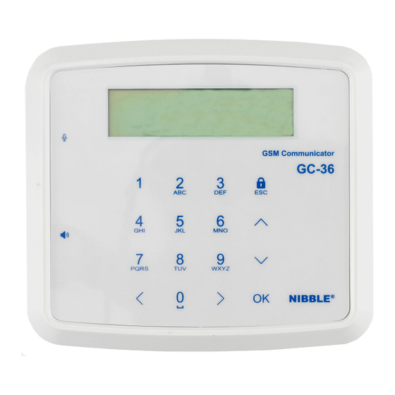
4 Functionalities 4.1 Local user interface The GC-36 module can be configured via its local user interface, made up by a capacitive keypad with 16 buttons, an alphanumeric LCD screen with 2x16 characters, as shown in figure 4. Section 5 details menu navigation. -
Page 12: Sms Configuration
3 access code loss, contact your distributor. 4.3 SMS configuration The GC-36 module can be configured via SMS commands. The module must have an active SIM card in order to allow configuration access. Section 6 details all SMS commands. -
Page 13: Automatic Test Calls
SMS for that input is sent to the phone that made the call. A possible use for this feature is the activation/deactivation of an alarm. If there is any configuration for that input, it is processed normally. The GC-36 executes this functionality whether the system is armed or disarmed. -
Page 14: Tamper Detection
SMS contents can be configured locally or via PC. 4.10 Arming and disarming the system The GC-36 can be armed and disarmed with access level 1. When the system is disarmed, all inputs and tamper detection are deactivated, that is, all events associated with inputs and tamper detection are not evaluated, except the feature of output actuation with costless phone call. -
Page 15: Local Configuration
User Manual Version 1.9 5 Local configuration Figure 5 shows a diagram of how to navigate the menu. From the locked screen a user can: • Arm the system, pressing the button with the lock symbol (see figure 4); • Disarm the system by inserting the disarm code; •... -
Page 16: Configuration Menu
User Manual Version 1.9 5.1 Configuration menu In the configuration menu the user can: 1. Configure I/O; 2. Configure phonebook; 3. Configure tamper detection; 4. Configure clock; 5. Configure access codes; 6. Configure voice messages; 7. Configure the system; 8. Configure GSM. 5.1.1 Configure I/O This submenu allows for I/O configuration as inputs or outputs, The character ‘I’... -
Page 17: Configure Tamper Detection
User Manual Version 1.9 5.1.3 Configure tamper detection This submenu allows for activation and deactivation of tamper. The tamper activation must be done only after device installation on the desired place, as it will be calibrated there. The tamper detection component is located in the back of the device next to the USB connector. -
Page 18: Technical And Configuration Commands
User Manual Version 1.9 All SMS commands follow the base structure shown in table 3. It consists of 3 fields separated by a comma (‘,’). [PIN_CODE],[CMD],[ARGS] Table 3: SMS commands base structure All commands start with the [PIN_CODE] field which is the level 3 access code with 6 digits (except when otherwise stated), followed by the [CMD] field which identifies the command and [ARGS] field which includes all arguments necessary for the command. -
Page 19: Configure Names Of I/Os
User Manual Version 1.9 Example Response Description I/O 1, 2, 3 and 6 configured as inputs 123456,IO,IIIOOI I/Os configured and 4 and 5 as outputs. I/O States: I/O1: Input I/O2: Input I/O3: Input 123456,IO Read current I/O configuration. I/O4: Output I/O5: Output I/O6: Input Table 7: I/O configuration example... -
Page 20: Configure Outputs Actions On Input Events
User Manual Version 1.9 If [TEXT_UP] and [TEXT_DOWN] are omitted, the module responds with the input’s current configuration. [PIN_CODE],IONUD,[IO],[TEXT_UP],[TEXT_DN] Table 11: SMS alerts configuration command Field Description The index, 1 to 6, of the I/O to be configured. TEXT_UP The text associated with input activation. The text associated with input deactivation. -
Page 21: Phonebook - Configure Sms Alerts
User Manual Version 1.9 Field Description The index, 1 to 6, of the I/O to be configured. Code for output N action. Table 16: Fields to configure output actions in on input events Example Response Description Configuration of outputs actions for input 1 activation: 123456,OUP,1,XXXLPX Outputs changed for input 1... -
Page 22: Phonebook - Configure Voice Alerts
User Manual Version 1.9 Example Response Description Inputs SMS alerts configuration for number 919999999: - Input 1: Sends on positive 123456,PS,919999999,PNBXXV SMS Inputs changed - Input 2: Sends on negative - Input 3: sends on both edges - Input 6: Sends as voice backup SMS Input Num. -
Page 23: Phonebook - Configure Actions On Outputs
User Manual Version 1.9 Example Response Description Inputs voice configuration for number 919999999: - Input 1: Sends on positive 123456,PV,919999999,PNBXXB Voice Inputs changed - Input 2: Sends on negative - Input 3: Sends on both edges - Input 6: Sends on both edges Voice Input Num. -
Page 24: Phonebook - Configure All Actions And Events
User Manual Version 1.9 Example Response Description Configuration of outputs actions for number 919999999: 123456,PO,919999999,XXXPNX Number’s outputs changed - Output 4: Positive pulse - Output 5: Negative pulse Outputs Num. 919999999: Read outputs actions configuration I/O4: Positive pulse 123456,PO,919999999 for number 919999999. I/O5: Negative pulse Table 29: Examples of outputs actions configuration 6.1.8 Phonebook –... -
Page 25: Usage And Actuation Commands
User Manual Version 1.9 [PIN_CODE],CT,[PER] Table 33: Command for test call configuration Field Description Test call period. Table 34: Fields for the configuration of test call period Configuration code Description Don’t send. Daily. Weekly. Monthly. Table 35: Test call configuration Example Response Description... -
Page 26: Change Level 3 Access Code
User Manual Version 1.9 6.2.2 Change level 3 access code It is possible to change the level 3 access code. [CMD] field is PIN. [ARGS] field is [NEW_PIN] which is the 6 digit code that will replace the current code. All level 3 access commands after this one must use the new access code. -
Page 27: Ambient Sound Call
User Manual Version 1.9 • PNUM – Read position of a number in the phonebook; • PPOS – Read number from a position in the phonebook; • PDN – Delete a number in the phonebook; • PAP – Add a number to a position in the phonebook; •... -
Page 28: Arm/Disarm The System
User Manual Version 1.9 6.2.6 Arm/disarm the system It is possible to arm and disarm the complete system or a single input with the SS command. The argument [ARM] is the code to arm/disarm and the argument [IO], if applicable, id the input to arm/disarm (see table 51). -
Page 29: Diagnostic
Table 56: Command for diagnostic Example Response Description Global state: SIM card balance: 4,80 EUR Signal quality: Good IMEI: 868325020946499 123456,ST Read the global system status Power: On Bat.: 80% FW version: 1.0.0 Model: GC-36 Table 57: Example for diagnostic 29 / 33... -
Page 30: Pc Configuration
7 PC configuration 7.1 Connection and diagnostic To configure GC-36 with the Windows software GC Configurator, the module must be powered by an external power supply and then connected to the PC with a micro-USB cable, and afterwards press button File->Connect, insert the level 3 access code(factory default ‘123456’) and press OK in the new window. -
Page 31: General Settings
User Manual Version 1.9 7.2 General settings In the Settings window it is possible to configure: • Device language; • Mode and number of tries for voice message alerts; • The SIM card as prepaid or postpaid, if balance is sent in SMS and in input alerts and the command to check balance;... -
Page 32: Inputs Configuration
User Manual Version 1.9 Figure 8: GC Configurator – I/O configuration 7.4 Inputs configuration In the Inputs/Outputs window it is possible to configure, for each input, in the input 1 to Input 6, tamper and power supply tabs: • Action on each output on input activation or deactivation; •... -
Page 33: Phonebook Management
User Manual Version 1.9 Figure 9: GC Configurator – Input configurations 7.5 Phonebook management In the Phonebook window it is possible to configure for each number: • The phone number; • The SMS alerts sending for each input; • The voice alerts sending for each input; •... -
Page 34: Event Logs
User Manual Version 1.9 Figure 10: GC Configurator – Phonebook management 7.6 Event logs In the Event log window it is possible to: • Download all the device’s event logs by pressing Read; • Delete all the device’s event logs by pressing Delete; •... -
Page 35: Firmware Update
User Manual Version 1.9 7.9 Firmware update The GC Configurator allows for module firmware update. To update access File->Update firmware and choose the appropriate firmware. After sending the update file, the module will reboot automatically and the GC Configurator will lose connection. Wait a few minutes and retry connection. -
Page 36: Legal Conditions
Damages and losses NIBBLE is not liable for damages or losses that may arise from the use of its products. NIBBLE’s liability for any claim based on breach of contract, negligence, breach of any right or responsibility in the product shall not exceed the amount paid to NIBBLE for that product.
Need help?
Do you have a question about the GC-36 and is the answer not in the manual?
Questions and answers