Advertisement
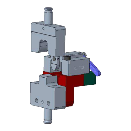
Figure 1: Crimping Die and Terminal Locator Assembly for HVP800-90 Terminals
1
Introduction
The crimping die assemblies listed in Table 1 are designed to be installed into the modular tool holders listed in
Table 1. The crimping die assemblies are designed to crimp HVP800-90 Terminals. Refer to application
specification
114-94083
for detailed information about these terminals.
Crimping die
assembly
2359761-1
2359762-1
NOTE
Dimensions in this instruction sheet are in millimeters with [inches in brackets]. Figures are for reference only and are not
drawn to scale.
Read these instructions thoroughly before crimping connectors.
© 2023 TE Connectivity Ltd. family of companies.
All Rights Reserved.
TE Connectivity, TE connectivity (logo), and TE (logo) are trademarks. Other logos, product, and/or company names may be trademarks of their respective owners.
Crimping Die and Terminal Locator
Assembly for HVP800-90 Terminals
Table 1: Crimping die assemblies
Wire size
16.0 mm2
25.0 mm2
35.0 mm2
50.0 mm2
PRODUCT INFORMATION +1 800 522 6752
Terminal
Modular tool
part number
holders
2355358-3
2305470-1
2326378-1
2-2141211-2
3-2141211-2
This controlled document is subject to change.
For latest revision and Regional Customer Service,
visit our website at www.te.com.
Instruction Sheet
408-35334
16 APR 2023 Rev A
1 of 6
Advertisement
Table of Contents

Related Manuals for TE Connectivity 2359761-1


Summary of Contents for TE Connectivity 2359761-1
- Page 1 1 of 6 For latest revision and Regional Customer Service, All Rights Reserved. visit our website at www.te.com. TE Connectivity, TE connectivity (logo), and TE (logo) are trademarks. Other logos, product, and/or company names may be trademarks of their respective owners.
- Page 2 408-35334 Description Each die assembly consists of a crimper, anvil, wire stopper, and terminal locator assembly (Figure 2). NOTE The terminal locator assembly is designed to maintain terminal position during the crimping process and is supplied pre- assembled to the crimping die. Figure 2: Components Shank Handle...
- Page 3 408-35334 Installing and removing the die assembly For information concerning die installation or removal, or general performance of the Modular Tool Holder, refer to the applicable 408 series instruction sheet packaged with the tool holder (Table 2). Table 2: Instruction sheets Modular tool holder Instruction sheet 2305470-1...
- Page 4 408-35334 Crimping For wire strip length and specific crimp information for each terminal being crimped, refer to the 114 series application specification listed in section 1. CAUTION If the tool holder is equipped with a crimp height (fine adjust) adjustment, you can prevent damage to the terminator, modular tool holder, or die assembly by starting at setting A on the crimp disc and incrementally adjusting to the specified crimp height.
- Page 5 408-35334 5. Open the wire clamp by pressing down on the wire clamp lever (Figure 5). Figure 5: Wire clamp lever 6. Insert the properly stripped wire into the wire barrel of the terminal. 7. Release the lever to clamp the wire in place. 8.
- Page 6 Call +1 800 522 6752. Write to: CUSTOMER SERVICE (038-035) TE CONNECTIVITY CORPORATION PO BOX 3608 HARRISBURG PA 17105-3608 For customer repair services, call +1 800 522 6752. Revision summary Since the last revision of this document, the following changes were made: ...
Need help?
Do you have a question about the 2359761-1 and is the answer not in the manual?
Questions and answers