Advertisement
Quick Links
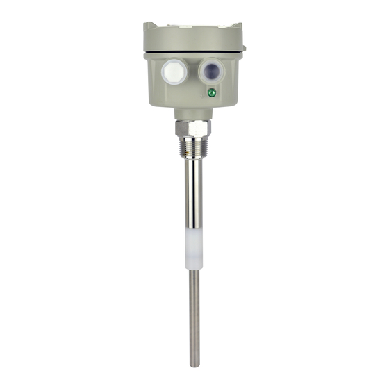
SA140 CAPACITANCE LEVEL SWITCH OPERATION MANUAL
WORKING PRINCIPLE
Capacitance switches rely on electrical capacitance theory (the ability of a
medium to store electrical energy). The switch detects a level change of a
tanks medium by calculating the capacitance between the tank wall and the
probe. All mediums have differing conductivity and dielectric constants which
affects their energy sstorage capability. When the probe comes into contact
with the medium, it can detect a change in the surrounding capacitance and
this actuates the switch accordingly.
KEY FEATURES AND BENEFITS
Capacitance switches are simple structures with no moving parts reducing wear and tear. Can be
applied to solids, powders, slurries and liquids. A variety of mounting options makes installation simple.
Remote capacitance switches are available for tanks with vibrators and prevent circuit board damage.
SPECIFICATIONS
Model number
SA140A
Power supply
110/220Vac±10%
Power
consumption
SPDT
Output
5A/250Vac/30Vdc
Ambient temp.
Operating temp.
Operating
pressure
Delay
Sensitivity range
PANEL INSTRUCTIONS
SA140A
SA140B
INDICATOR
INDICATOR
DELAY
SENSITIVITY ADJ
ON
ON
H
L
H
SERIES No.
SW 1 2 3 4 5 6
SW 1 2 3 4 5 6
SENSITIVITY-No.
COARSE
COARSE
E
S
COM
NO
NC
AC0V
110V
220V
E
S
8
8
Power supply
Output
Sensitivity
Level indicator
8
Connect with probe connection
SA140B
SA140C
24V±20%
24V±20%
2W
SPDT
Transistor output
5A/250Vac/30Vdc
-20~60°C
-20~80°C
20kg/cm
0~8s±1S
14.6pF
SA140C
INDICATOR
DELAY
DELAY
SENSITIVITY ADJ
ON
L
H
L
SERIES No.
SERIES No.
SW 1 2 3 4 5 6
SENSITIVITY-No.
SENSITIVITY-No.
COARSE
COM
NO
NC
0V
24V
E
S
O/P
0V
8
Coarse position
Time delay setting
WIRING INSTRUCTIONS
1. Probe has not come into contact with medium – LED off NC and COM terminals are connected
(usually referred to as B)
2. Probe contacts medium: LED turns on without delay NO and COM terminals are connected (referred
to as A)
Operation mode
WIRING PRECAUTIONS
1. Turn off power before wiring.
2. If working on live circuits, wear insulated gloves and insulated shoes.
3. Use insulating tape when appropriate.
4. Check for the presence of water within the junction box cover, cable connectors and take good
waterproofing measures.
E
S
wire to sensor probe
SA140A(SPDT output wiring)
INSTALLATION (SEE THE SKETCH BELOW)
1. Top mounted: Minimum distance should
be 300mm between the probe and wall.
2. The insulated probe should protrude at
least 30mm from the tank wall.
3. Side mounting angle: roughly 20
degrees.
4. The conduit and wiring should face
downward.
24V
NPN output
RELAY output
Indicator LED
O/P
Red
COM.
O/P
Red
COM.
COM NO
NC AC0V 110V 220V
E
S
COM NO
NC
wire to sensor probe
SA140B(SPDT output wiring)
N.O.
N.C.
N.O.
N.C.
E
S
O/P
0V
24V
0V
24V
-
-
+
+
POWER
POWER
+
R
wire to sensor probe
SA140C(SPDT output wiring)
300mm
30mm
No induction body
20°
Advertisement

Related Manuals for FineTek SA140


Summary of Contents for FineTek SA140
- Page 1 SA140 CAPACITANCE LEVEL SWITCH OPERATION MANUAL WIRING INSTRUCTIONS 1. Probe has not come into contact with medium – LED off NC and COM terminals are connected (usually referred to as B) WORKING PRINCIPLE 2. Probe contacts medium: LED turns on without delay NO and COM terminals are connected (referred...
- Page 2 Correct any wiring issues 6=6.8p, total 14.6pF. Increase the dielectric value to decrease the sensitivity. Decrease the problem Level changes but dielectric value to Increase the sensitivity. Dusty, powdery Switch to FineTek static Static electricity damage switch doesn't environment model actuate...