
Related Manuals for Wellsys i16


Summary of Contents for Wellsys i16
- Page 1 (aka WS16000) MANUAL Quench USA Inc. 630 Allendale Road, Ste200 King of Prussia, PA 19406 (800) 288-1891 www.wellsysdealers.com...
- Page 2 Products manufactured and marketed by Wellsys and its affiliates are protected by patents issued or pending in the United States and other countries. Wellsys reserves the right to change the specifications referred to in this literature at any time, without prior notice. Changes or modifications not expressly approved by Wellsys could void the warranty and user’s authority to operate the equipment.
-
Page 3: Table Of Contents
• Display and Control Panel ............10 • Operating Instructions ............11 • Warranty ................12 SERVICE GUIDE • Service Requirements ............13 • i16 Parts List…………………… ............. 14 • Flow Diagram ................. 23 • PCB Diagram ................24 INSTALLATION GUIDE • Pre-Installation Procedures ........... 25 •... -
Page 4: Safety Alert Symbols
Unit should be protected by ground-fault circuit interrupter (GFCI) or residual current device (RCD) having a rated residual operating current not exceeding 30mA. Use only Wellsys supplied power cord. Never use extension cords or power strips to connect unit. Do not use if the power supply cord is damaged. - Page 5 WARNING! DO NOT OPERATE IF DAMAGED. Unplug and isolate water supply if abnormal conditions exist. Contact Wellsys or authorized dealer for repair, service, and installation to avoid hazards. WARNING! HOT WATER. Unit produces Hot Water in excess of 80 C (175 F).
-
Page 6: Features And Benefits
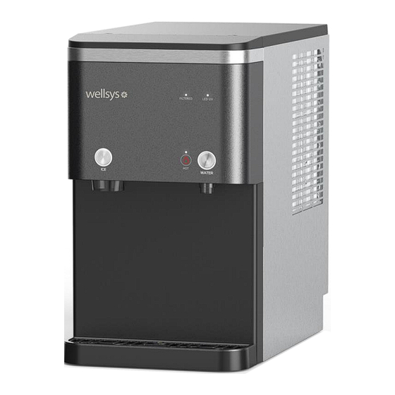
Ice Storage and Water Capacity The i16 Water Treatment System has 1.25 liters of Hot Water and can hold up to 16.5lbs of Ice. Large Dispense Area with Recessed Faucet 11-inch dispense height with recessed faucet to protect from cross-contamination. -
Page 7: Certifications
CERTIFICATIONS i16 Water Treatment Systems have been tested and certified to rigorous NSF and UL Standards. We believe that performance testing and certifications validate Wellsys as a world- leader in water treatment systems. Wellsys I16 Component Certifications Include: UL399 – Certified Drinking Water Cooler Intertek Labs (ETL) Certified the i16 Water Treatment System to ANSI/UL 399 Standard for Drinking Water Coolers. -
Page 8: Model Designations And General Specifications
MODEL/PART DESIGNATIONS MODEL - BRAND NAME DESCRIPTION PART NUMBER i16 – Hot, Ambient, Ice i16 Countertop Unit Z10534-(YYMMDD)-00XXX SPECIFICATIONS ITEM Water Connection ¼” Quick Connect Rate Voltage AC 120V/60Hz Power Consumption 4.9A (565W) Power Cord 1.9m (6.3ft) IP Class IPX1 Climate Class N Class (32°C +/- 1°C) (89.6°F +/- 33.8°F) -
Page 9: Shipping Specifications
SHIPPING SPECIFICATIONS ITEM 358mm W x 603mm D x 699mm H Width/Depth/Height 14.1”W x 23.75”D x 27.5”H Weight (dry) 93lbs. (42.0 kg) 23.6” 23.6” 14.2” i16 Manual Page 9 - Revision: 2-09-2023... -
Page 10: Display And Control Panel
DISPLAY & CONTROL PANEL i16 Manual Page 10 - Revision: 2-09-2023... -
Page 11: Operating Instructions
OPERATING INSTRUCTIONS The below pictures show the front user interface (UI) and control panel for the i16 Water Treatment System. For Ice: Press the “Ice Dispense” button. While holding the button, the Ice LED will blink, and ice will dispense. Release to end. -
Page 12: Warranty
Wellsys will, at its sole discretion, determine whether to correct the defect or replace the unit, free of charge to you. If Wellsys determines that the unit should be returned for warranty service, Wellsys will approve of return in writing and will issue a Return Authorization which you must obtain prior to shipping the product. -
Page 13: Service Requirements
4. Clean and sanitize external surfaces of the I16 Water Treatment System. Use soap and water or chemicals that are compatible with ABS plastic and will not damage or degrade the product surfaces. -
Page 14: I16 Parts List
PARTS LIST Common with i15 Parts Part No. Description Photo 61-2231-0 EPS PAD LOWER (CH5) 91-4362-0 ASSY PLATE BASE ASSY (HC5) 31-0431-0 CAP DRAIN (BLACK) 41-2207-0 ICE MELT PUMP 41-1405-0 DRAIN PUMP 91-4372-0 TUBING 3/8 PERT ASSY 11-2330-0 STEM TAIL TEE ¼... - Page 15 41-2048-0 POWER CORD PLUG B 45-0024-0 COMPRESSOR NF21K5111CW/CH1 21-0975-0 BKT AUGER LOWER (HC5) 21-0851-0 BKT AUGER UPPER 21-0867-1 AUGER 21-0892-0 WRENCH BOLT 21-0893-0 WASHER 21-0848-0 CUTTER AUGER i16 Manual Page 15 - Revision: 2-09-2023...
- Page 16 41-2092-0 MOTOR FAN 61-2228-0 EPS AUGER (HC5) 41-0949-2 AUGER SOLENOID 41-1768-4 HOT WATER VALVE SOLENOID 41-2209-0 DISPENSE PUMP 91-3665-1 WATER TANK ASSY 31-0721-1 TU ELBOW AIR VENT 41-1432-2 WATER LEVEL SENSOR (2PIN) i16 Manual Page 16 - Revision: 2-09-2023...
- Page 17 RESERVOIR TANK LOW LEVEL SENSOR 31-0325-1 COLD WATER LEVEL SENSOR RING 11-2985-0 COVER TANK WATER 31-0437-0 SEAL COVER TANK WATER 51-0347-1 FILTER 6” SED 91-4429-0 MANIFOLD FAUCET ASSY 91-4446-0 HOT TANK ASSY (HC) i16 Manual Page 17 - Revision: 2-09-2023...
- Page 18 BUSHING SPIRAL SUS RIGHT (HC5) 11-3388-0 BUSHING SPIRAL SUS LEFT (HC5) 11-3387-0 BASKET ICE (HC5) 41-2058-0 SENSOR ICE FULL LASER 41-2059-0 SENSOR ICE FULL LASER 61-2183-0 EPS UNIT LEFT (HC5) 41-2318-0 LEVEL SENSOR (HC5) i16 Manual Page 18 - Revision: 2-09-2023...
- Page 19 91-4455-0 MOTOR GEARED ASSY (HC5) 21-0970-0 COUPLER MOTOR SPIRAL SUS LEFT (HC5) 11-3099-0 LINK DOOR ICE 91-3698-0 ASSY DOOR ICE 31-0422-0 SEAL DOOR ICE 41-1550-0 STERILIZER UV LED TANK 41-2057-0 MOTOR GEARED (HC5) i16 Manual Page 19 - Revision: 2-09-2023...
- Page 20 41-2319-1 PCB MAIN (HC5V.1) 21-0967-0 FRAME LEFT (HC5) 21-0854-1 FRAME REAR 21-0971-0 COVER REAR (HC5) 41-2055-0 2-STAGE SWITCH 21-0974-0 COVER PCB UPPER (HC5) 91-4367-0 COVER UNIT ASSY (HC5) 11-3391-0 COVER UNIT (HC5) i16 Manual Page 20 - Revision: 2-09-2023...
- Page 21 EPS COVER UNIT (HC5) 21-0972-0 COVER RIGHT (HC5) 21-0973-1 COVER LEFT (HC5) 91-4440-0 HC5 COVER FRONT ASSY (WELLSYS) 21-0849-0 BUTTON TOUCH CHOICE 11-3451-0 DECO COVER FRONT PRINT (WELLSYS, HC5) 41-2320-0 PCB DISPLAY #1 (SELECT, DISPENSE) i16 Manual Page 21 - Revision: 2-09-2023...
- Page 22 11-0431-0 FIT END PLUG ¼ 11-3402-0 COVER TOP (HC5) 91-3646-0 DECO FAUCET ASSY 11-0751-0 WATER DRAIN HOSE 11-3397-1 DECO DISPENSER (HC5-ICE) 61-2184-0 EPS PAD FRONT (HC5) 91-3614-0 TRAY ASSY i16 Manual Page 22 - Revision: 2-09-2023...
-
Page 23: Flow Diagram
WATER FLOW DIAGRAM i16 Manual Page 23 - Revision: 2-09-2023... -
Page 24: Pcb Diagram
PCB DIAGRAM DANGER! HIGH VOLTAGE ELECTRICAL HAZARD. PCB (Printed Circuit Board) contains High Voltage. Only trained and qualified technicians should attempt live testing. i16 Manual Page 24 - Revision: 2-09-2023... -
Page 25: Pre-Installation Procedures
Only qualified personnel who have read and understand this entire manual should attempt to install, or service this i16 Water Treatment System, failure to do so could result in death or serious injury. DO NOT plug into an electrical supply until specifically instructed. -
Page 26: Notes On Installation
*If it is blocked, the water will not flow smoothly to the unit, and may cause performance degradation. 8. Do not place any heating system near the rear of the unit. 9. The power supply and source water must be directly connected to the unit. i16 Manual Page 26 - Revision: 2-09-2023... -
Page 27: Installation
A. Connect the source line to the source on the outside of the filter box. B. Connect the drain to the drain on the outside of the filter box. C. Connect the secondary drain to the top of the TCR. i16 Manual Page 27 - Revision: 2-09-2023... - Page 28 P. Spray a light mist and then put the lid to the reservoir back on. Q. Reinstall the front panel and the top panel. 9. Connecting the Filters to the i16 (a 3-4 gallon bladder tank must be used as well). A. Mount the filter enclosure under the sink.
- Page 29 *Please secure the drain tubing to prevent any dislodgement during the drainage. Note: To ensure reliability and the highest performance, only genuine Wellsys filters should be used and must be changed on time. Please reference below for the filter change schedule.
- Page 30 Stand to secure the M6 hex bolts (x4). *After tightening, ensure it is stable and there is no danger of tipping or falling. 3. Once fixed, return the Drip Tray of unit and the Front Cover of Stand. i16 Manual Page 30 - Revision: 2-09-2023...
- Page 31 2. Drill two holes in the marked position to fix the bracket to the wall. 3. Ensure the unit is fixed with the wall-mounted bracket, so that the unit does not fall if pushed. i16 Manual Page 31 - Revision: 2-09-2023...
-
Page 32: Sanitizing
2. Clean the spout with a soft cloth and cleaning agent. After cleaning, put the spout cap back on the spout. 3. Insert the hook into the hole and push the spout upward. Make sure the front three hooks are properly inserted into the unit. i16 Manual Page 32 - Revision: 2-09-2023... - Page 33 7. Remove the Ice Tank Cover by loosening the fixing screws, and then remove 2 augers by pulling them upward, take care not to lose the caps of the augers. (During the re-assembling of spirals, please pay attention to the shape of the joint). i16 Manual Page 33 - Revision: 2-09-2023...
- Page 34 5. Open the Pink Hot Water Drain Valve Cap and connect the drain hose to the Hot Water Drain Valve, and then proceed to drain completely all cleaning solution. Once completed, remove the drain hose and replace the Pink Hot Water Drain Valve Cap to its original location. i16 Manual Page 34 - Revision: 2-09-2023...
- Page 35 24. Verify that water is dispensing from the hot tank before turning the Hot Tank Switch back on. If water does dispense from the Hot Tank, turn the Hot Tank Switch on. 25. Assemble the Top Cover and Water Tray. i16 Manual Page 35 - Revision: 2-09-2023...
- Page 36 2. Properly dispose of used cleaner, sanitary gloves, etc. after cleaning. 3. Make sure tank cover is closed firmly and is installed properly. 4. Clean up the tank regularly every 6 months to a year. i16 Manual Page 36 - Revision: 2-09-2023...
-
Page 37: Resetting Hot Tank Overload Thermostat
If water flows from the hot tank, the tank is primed and full of water. Continue with resetting the thermostat. Water will begin heating, and hot water should be available within 5-10 minutes. i16 Manual Page 37 - Revision: 2-09-2023... -
Page 38: Troubleshooting Guide
Change from an RO setup to a filtered setup or address issues with RO system. (Note: low water pressure will also cause the RO to waste more water as it attempts to fill the bladder tank, which will also reduce the life of the pre-filters.) i16 Manual Page 38 - Revision: 2-09-2023... - Page 39 Sensor is located on top of the gear motor. If it fails, or if the gear RPM Sensor Error or Failure motor slows down due to hardness in the evaporator, it will shut down ice production. Hardness in the evaporator will cause ice to i16 Manual Page 39 - Revision: 2-09-2023...
- Page 40 ▪ 500 Tap TDS at 80% reduction = 100TDS product water ▪ With the mineral add back filter a high concentration of calcium will negatively impact the amount of scale that will, as a result, negatively impact ice systems. i16 Manual Page 40 - Revision: 2-09-2023...
- Page 41 For large usage account with larger bladders, it may be necessary to have additional filter banks to improve the recovery time. o Please note that when doing this a booster pump may become necessary even if there a tap pressure of 60psi. i16 Manual Page 41 - Revision: 2-09-2023...
- Page 42 • Locate the Hot Tank Power Switch on the back of the machine and switch it on. Hot Tank Power Switch is off i16 Manual Page 42 - Revision: 2-09-2023...
Need help?
Do you have a question about the i16 and is the answer not in the manual?
Questions and answers
what size is the drain line