
Related Manuals for Panasonic WJ-FS616C


Summary of Contents for Panasonic WJ-FS616C
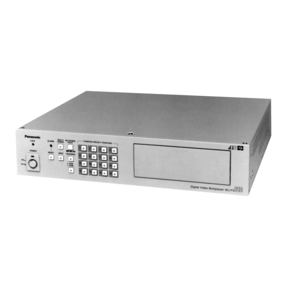
- Page 1 Video Multiplexer WJ-FS616 Before attempting to connect or operate this product, please read these instructions completely...
-
Page 2: Table Of Contents
PREFACE ... 1 FEATURES ... 1 PRECAUTIONS ... 2 MAJOR OPERATING CONTROLS AND THEIR FUNCTIONS ... 3 INSTALLATIONS ... 10 SYSTEM CONNECTIONS ... 14 SETUP MENU ... 21 Setup Menu ... 22 Alarm Setup Menu ... 23 Multiscreen Output Menu ... 25 Spot Output Setup ... -
Page 3: Preface
RS- 232C interface or the wired remote control terminal of the Panasonic Time Lapse VCR. • The WJ-FS616 can be controlled from a PC or the WV-CU550A System Controller via RS-232C or RS- 485 interface. -
Page 4: Precautions
PRECAUTIONS • Refer all work related to the installation of this product to qualified service personnel or system installers. • Do not block the ventilation opening or slots on the cover. To prevent the appliance temperature from rising, place the appliance at least 5 cm (2 inches) away from the wall. -
Page 5: Major Operating Controls And Their Functions
FUNCTION PRE-POSI STILL 1. Power Switch (POWER ON / OFF) This switch turns the power of the video multiplexer on or off. The LED lights up when the power is turned on. Caution: The LED indicator blinks to indicate an abnormality of the cooling fan in this appliance. - Page 6 This button is used to select the multiscreen pattern to be displayed on the multiscreen monitor while monitoring the camera picture or VCR playback picture. Pressing this button repeatedly will switch the screen as follows: Camera Picture: 4 7 9 10 13 16 4 screen segments...
- Page 7 32. Lock Switch (LOCK OFF / ON) This switch can be used to lock out operation of the video multiplexer panel controls. While this switch is in ON position, control from the video multiplexer is disabled.
- Page 8 55. Power Cord 56. Signal Ground Terminal (SIGNAL GND) 57. Termination Switch (TERM., OFF / ON) This switch is used to enable termination of the video multiplexer’s data port. 58. Data Port (DATA, OUT / IN) These ports are used to exchange control data with the WV-CU550A System Controller or a PC in a sys- tem.
- Page 9 System Controller WV-CU550A Note: When using this controller in combination with the WJ-FS616, cover the panel of the controller with the panel tem- plates provided. ALARM BUSY MULTISCREEN RESET ZOOM SELECT ALL FS RESET PRE- HOME/– AUTO/+ FUNCTION POSI STILL AUX1 AUX2 DATA TERM.
- Page 10 1. Alarm Indicator (ALARM) This LED indicator (Red) lights up to indicate that an alarm condition exists. It goes off when the alarm is reset automatically. To turn the indicator off, press the ALARM RESET button. 2. Busy Indicator (BUSY) This LED lights up to indicate that the system is locked by PC command.
- Page 11 “ON” position. 25. Controller Unit Number Switch (CONTROLLER UNIT NO. 1-8) This switch is used to identify the unit number of the System Controller. When combined with the WJ-FS616 Video Multi- plexer, set this switch to the “0” position.
-
Page 12: Installations
Multiplex Boards, which includes four control boards. Caution: Before installing boards, be sure to turn off the Power Switch of the video multiplexer. 1. Remove the six screws on the top cover of the video multiplexer as shown below. Rear 2. -
Page 13: Tally Output Setting
6. Set the jumper connector, located at the top left of the board to be installed, to the position shown below. Jumper Connector Board Connector Initial State Installed State 7. Insert the board and confirm that the position is cor- rect. -
Page 14: Dip Switch Setting
SW 1 to the position shown below. 1. Disassemble the video multiplexer as described for installing the Data Multiplex Boards on page 10. 2. Set switch (SW1) on the board to the position shown above. 100 ms or more... - Page 15 WV-CU550A System Controller Modifying the Front Panel 1. Peel the tape off the supplied panel templates, then attach them on the front panel of the System Controller. 2. Peel off the label and attach it on the rear of the System Controller as shown below.
-
Page 16: System Connections
SYSTEM CONNECTIONS Shown below is an example of a basic system connection. Alarm Sensor MULTI MULTISCREEN ALARM SCREEN SELECT LOCK POWER RESET SPOT SEQUENCE System Controller WV-CU550A Video Multiplexer WJ-FS616 CAMERA/PRESET POSITION PUSH OPEN RS-232C/Wired Time Lapse VCR System Controller for WJ-FS Personal Computer (Software) Basic System Connection... -
Page 17: Connection With The Camera Sites
Connection with the Camera Sites Connect cameras (or camera site equipment) data multiplexed type to the CAMERA IN connectors 1 through 4 on the rear panel of the Video Multiplex- Note: Make sure that the cable length between the camera site and the WJ-FS616 Video Multi-plex- er is less than 900 m (3 000 ft) when using RG- 59/U, BELDEN 9259 or equivalent cables. -
Page 18: Connections For Rs-485 Type Camera
Note: Recommended for RS-485 communication is shielded, two-wire, twisted pair, low impedance cable, AWG#22 or thicker. (1) Connect with single RS-485 camera as shown below, setting the LINE SELECT switch to “2” or “4”. WV-RM70 and others TERM DATA T(A) T(B) R(A) R(B) RS485 TERM. -
Page 19: Connection With The Monitors
Connection with the WV-CU550A System Controller Setting the Termination and Controller Unit Number The Termination Switch and the Controller Unit Number Switch are located on the rear of the FS616 end System Controller. When combined with the WJ-FS616 Video Multi- plexer, always keep these switches in the positions shown below. -
Page 20: Connection With Alarm Sensors
Connection with Alarm Sensors Connect the sensor switches to the Alarm/Remote (ALARM/REMOTE) Control Connector on the rear of the Video Multiplexer as shown in the example below. Pin No. ALARM/REMOTE SW16 Notes: • Alarm inputs simultaneously or at very short intervals will be ignored. Allow for an interval of at least 100 ms from one alarm input to the next. -
Page 21: Connection With The Time Lapse Vcr
Connection with the Time Lapse VCR Connect the Time Lapse VCR as shown in the example below. CAMERA REC OUT SW IN VIDEO S–VIDEO VIDEO IN CAMERA SW OUT ALARM ALARM WARNING SERIES REC IN SERIES 1 SHOT IN HUMID OUT REC OUT ALARM TIME... -
Page 22: Connection With External Remote Control Switches
• Pin#6, Sequence SW for Spot Output and the Pin#8, Alarm Recover Input can also accept DC voltages of 5 V (high level) and 0 V (low level) besides the switch contact signals. The Multiplexer recognizes falling edge (high to low transition) as an input. -
Page 23: Setup Menu
SETUP MENU The Setup Menu provides a way for controlling func- tions not available through direct input. Displaying the SETUP MENU 1. Confirm the camera and peripherals are connected correctly and securely. 2. Turn on the power switches of all system compo- nents. - Page 24 Setup Menu As shown below, the SETUP MENU has nine main sub menus: Alarm Setup, Multiscreen Output Menu, Spot Output Setup, Record Output Setup, Multiscreen 2 Output Setup, System Setup, Camera Download, Camera Upload and All Rese. Six of these sub menus; Alarm Setup, Multiscreen Output Setup, Spot Output Setup, Record Output Setup, Multiscreen 2 Output Setup and System Setup, are further divided into additional submenus.
-
Page 25: Alarm Setup Menu
Alarm Setup Menu WJ-FS616 SETUP MENU ALARM SETUP * MULTI OUTPUT SETUP * SPOT OUTPUT SETUP * REC/MULTI2 REC OUTPUT * SYSTEM SETUP * CAM DOWNLOAD CAM UPLOAD ALL RESET SELECT * Move the cursor to ALARM SETUP on the SETUP MENU, then press the SET button. -
Page 26: Alarm Display On The Monitors
4. Camera Switching Pulse Loss Alarm This item lets you enable or disable alarm display on the monitor screen when the camera switching pulse is lost. 1. Move the cursor to the SW-LOSS ALM parame- ter. 2. Select ON or OFF by pressing the LEFT or RIGHT button. -
Page 27: Multiscreen Output Menu
MODE 0. MODE 0: Normal Recording MODE 1-8: Time Lapse mode without camera switching pulse. MODE 9: Time lapse mode with camera switch- ing pulse. After finishing the setting, press the SETUP/ESC button to return to the previous SETUP MENU. -
Page 28: Camera Display Position Setting
2. Clock Display Setting This item lets you enable or disable the clock dis- play on the Multiscreen Monitor. 1. Move the cursor to the CLOCK DISPLAY para- meter. 2. Select ON or OFF by pressing the LEFT or RIGHT button. The initial factory setting is ON. ON: Enables clock display on the monitor screen. -
Page 29: Spot Output Setup
Spot Output Setup WJ-FS616 SETUP MENU ALARM SETUP * MULTI OUTPUT SETUP * SPOT OUTPUT SETUP * REC/MULTI2 REC OUTPUT * SYSTEM SETUP * CAM DOWNLOAD CAM UPLOAD ALL RESET SELECT * Move the cursor to SPOT OUTPUT SETUP on the SETUP MENU, then press the SET button. -
Page 30: Recording Mode
2. Clock Display This item lets you enable or disable recording of the clock display on the VCR. 1. Move the cursor to the CLOCK DISPLAY para- meter. 2. Select ON or OFF by pressing the LEFT or RIGHT button. The initial factory setting is ON. ON: Enables recording of clock display on the VCR. -
Page 31: Multiscreen 2 Output Setup
4. Press the SET button to move the cursor to the recording mode title area. The square cursor appears in the character table. 5. To select a character, move the cursor on the desired character in the table by pressing the Direction Arrow buttons. -
Page 32: System Setup
System Setup WJ-FS616 SETUP MENU ALARM SETUP * MULTI OUTPUT SETUP * SPOT OUTPUT SETUP * REC/MULTI2 MULTI2 OUTPUT * SYSTEM SETUP * CAM DOWNLOAD CAM UPLOAD ALL RESET SELECT * Move the cursor to SYSTEM SETUP on the SETUP MENU, then press the SET button. -
Page 33: Camera Title Display Position
Press the FUNCTION button to display the next page, then press this button again to return to the previous page. 2. Move the cursor to the channel you want to edit, then press the SET button. The cursor moves to the title area, and the square cursor appears on the character table. - Page 34 Preset Position 1. Move the cursor to the step number you want to edit in the PRE area by pressing the Derection Arrow Buttons. 2. Select the desired preset position number in the PRE area by pressing the Increment (+) or Decrement (–) button.
-
Page 35: Lock Mode
8. Lock Mode This item lets you decide which buttons will be locked while the LOCK switch is in ON position. 1. Move the cursor to the LOCK MODE parameter. 2. Select ALL or VCR by pressing the LEFT or RIGHT button. -
Page 36: Alarm Terminal Setup
9. Cable Compensation/VD2/ Data This item lets you select the optimum setting for the cable-loss compensator and whether to supply the VD2 (sync) signal or control data to the camera. Note: These settings will work only for the input channels that have the multiplex feature with the Data Mutiplex Board WV-BP6164 installed. -
Page 37: Communication Port Setup
11. Playback Mode This item lets you select the ID code for playback of recorded video tape. 1. Move the cursor to the PLAYBACK MODE para- meter. 2. Select FIELD or FS10 by pressing the LEFT or RIGHT button. The initial factory setting is FIELD. FIELD: Normal position. -
Page 38: Vcr Input Select
15. VCR Input Select This item lets you select the VCR input terminal. 1. Move the cursor to the VCR IN SELECT para- meter. 2. Select VIDEO or S-VIDEO by pressing the LEFT or RIGHT button. VIDEO: Selects input from the VCR VIDEO ter- minal. -
Page 39: Camera Upload
Camera Upload This item lets you upload camera setup data from the Video Multiplexer’s memory to a camera. 1. Move the cursor to the CAM UPLOAD parameter in the SETUP MENU. 2. Select YES by pressing the LEFT or RIGHT but- ton, then press the SET button. -
Page 40: Operating Procedures
MONITOR CONTROL FUNCTION Before starting the following procedures, all system components should be turned on. Then set the LOCK switch to the OFF position. Operating the Spot Monitor The following operations are available on the Spot Monitor. Displaying the Camera Picture 1. - Page 41 3. Electronic Zooming 1. Repeat the procedures described above for Single Spot. 2. Press the EL-ZOOM button to display the zoomed picture. The LED on the EL-ZOOM button lights up. EL-ZOOM ENTRANCE ENTRANCE 3. Press the UP, DOWN, LEFT or RIGHT button to move the picture in the desired direction.
- Page 42 ENTRANCE STILL Note: You can stilled multiple pictures on the multi- screen. 5. Press the blinking CAMERA button to cancel the Still function. 6. Press the STILL button again. The displayed pic- tures returns to normal viewing. The LED on the STILL button goes off. 6.
- Page 43 1. Single Spot 1. Repeat steps 1 and 2 above. 2. Press the desired CAMERA button (1 - 16) corre- sponding to the picture you want to display. The selected playback picture is displayed on the moni- tor screen. Note: •...
-
Page 44: Camera Control Function
FUNCTION The camera control is only available while the cam- era picture is displayed in Single Spot on the select- ed monitor screen and the LOCK switch is in OFF position. Camera Selection 1. Press the SPOT or MULTISCREEN SELECT but- ton. -
Page 45: Camera Setup
The following functions are available only with cam- eras that have preset panning functions, such as the Panasonic WV-BS500 or WV-CS600 series. Note: Select only preset position numbers 1 to 16. 1. Select the desired camera referring to the Camera Selection procedure described on page 42. -
Page 46: Alarm Control Function
The following functions are available only with cam- eras that have preset panning functions, such as the panasonic WV-BS500 or WV-CS600 series. 1. Press the FUNCTION button while the position setting menu is displayed. 2. Press the Direction Arrow buttons to move the pan/tilt head in the desired direction. -
Page 47: Record Output
4. Camera Preset Movement Enables movement of the camera to the preset posi- tion that was specified in the ALARM TERMINAL SETUP table of the SYSTEM SETUP menu. Refer to the setup on page 34. Record Output • Alarms are recorded in the mode specified for the ALM REC MODE parameter on the ALARM SETUP menu. -
Page 48: Example Of Using Multiscreen 2 Monitor
Alarm Reset Manual Reset When an alarm is activated, the Alarm Indicator blinks. The indicator keeps blinking until all alarms are cleared by pressing the ALARM RESET button. The blinking or lit indicator goes off. ALARM RESET Auto Reset The alarm is automatically reset after the pro- grammed Alarm Output Time has elapsed or the lost video signal has been recovered. -
Page 49: Other Functions
Alarm Suspension This function disables activation of the alarm link and instead enables recording of any alarm activat- ed in the alarm log. It is used to suspend the alarm link during camera setup. 1. Press the RESET and SPOT buttons simultaneously for more than two seconds to suspend the alarm. -
Page 50: Setup Menu Operations (With Wv-Cu550A)
SETUP MENU OPERATIONS (with WV-CU550A) During setup of the WJ-FS616 with the WV-CU550A System Controller, the following buttons and keys of the System Controller correspond with those of the WJ-FS616 as shown below. WJ-FS616 SET UP/ESC Press 2 sec more. LEFT HOME/SET RIGHT... -
Page 51: Operating Procedures (With Wv-Cu550A)
WJ-FS616 to the ON position to prevent false operation. MONITOR CONTROL FUNCTION 1. Press the Controller On/Off Switch located on the rear of the System Controller to the ON position. The display shown below appears on the System Controller’s LCD. -
Page 52: Camera Control Function
3. Pan/Tilt Control (Preset Operation) The following functions are only available with cam- eras that have preset panning functions, such as the Panasonic WV-BS500 or WV-CS600 series. 1. Select the desired camera referring to the Camera Selection above. 2. Press the PRE-POSI button, then select the preset number by pressing the numeric keys. -
Page 53: Alarm Control Function
The following functions are only available with cam- eras that have preset panning functions, such as the panasonic WV-BS500 or WV-CS600 series. 1. Press the ALT button while the position setting menu is displayed. 2. Move the joystick controller to move the pan/tilt head in the desired direction. -
Page 54: System Expansion
SYSTEM EXPANSION The system shown below is an example of the expansion capabilities of the WJ-FS616 Video Multiplexer. Up to four Video Multiplexers can be connected to expand the camera inputs. Main Site (Unit 1) Camera 1 -16 Video Multiplexer WJ-FS616 Spot In MULTI... -
Page 55: Other Applications
WV-CU550A System Controller. • Sequence display is limited to the cameras con- nected to one multiplexer unit only. • It is recommended to set the LOCK switch to the ON position while making these connec- tions. • For controlling more than 4 cameras, additional WV-BP6164 Data Multiplex Boards need to be installed in the Video Multiplexer. - Page 56 • Application 2 The camera pictures in the Local Site can be dis- played on the Multiscreen Monitor in the Main Site by connecting a coaxial cable shown below. Video Multiplexer REC OUT VIDEO S–VIDEO Local Site Coaxial Cable RG-59/U less than 250m (800 ft) Video Multiplexer PLAY IN MULTISCREEN OUT...
-
Page 57: Appendix
APPENDIX This Appendix details the elements for communication between the Video Multiplexer and the personal computer. For BAUD RATE, DATA BIT, STOP BIT and PARITY settings, see page 35 COM PORT SETUP menu. Communication Protocol 1. Transmission Command The PC sends messages to operate the Multiplexer in the format shown below. Also refer to the command table shown later. -
Page 58: Command Table
Command Table (1) Operation Control Transmission Item Command (ASCII) Monitor Select OMS : m VCR/Camera Select OVC : m Still ON/OFF OST : m : nn Multiscreen Select OTC : m Sequence OSQ : m Sequence Mode OSE : m Select Electronic Zoom OZM : m... - Page 59 (3) Cursor Control Transmission Item Command (ASCII) Cursor Movement DCR : mm Select Parameter *2 The parameter valid on the main unit setup menu is: mm=UU, DD, RR, LL, BB, ES, FF, IC, DC The parameter valid for zoom position move during electronic zooming is: mm=UU, DD, RR, LL, UR, UL, DR, DL (4) Status Inquiry Transmission...
- Page 60 Examples of response Response Command (ASCII) @mPLSNcc @mPLSZcc @mPLSScc @mPLSXcc @mPLSMLa @mPLQNcc @mPLQMLa @mPLQZcc @mPVSNcc @mPVSZcc @mPVSScc @mPVSXcc @mPVSMLa @mPVQNcc @mPVQMLa @mPVQZcc @mPRSMLa @mPE @mPX m=0, 1, 2 Monitor Number (0 : Spot Monitor, 1 : Multiscreen Monitor, 2 : Multiscrren 2 Monitor ) P=N, A, D, F N : Normal A : Alarm cc=01 - 16...
-
Page 61: Specifications
Specifications are subject to change without notice. STANDARD ACCESSORIES Rack Mounting Bracket ... 2 pcs. Screws (M4 x 10) ... 4 pcs. Switch Protector ... 1 pc. 120 V AC 60 Hz 50 W 1.0 V[p-p] /75 composite video signal 0.5 V[p-p] /75... - Page 62 Panasonic Security and Digital Imaging Company A Division of Matsushita Electric Corporation of America Executive Office: One Panasonic Way 3E-7, Secaucus, New Jersey 07094 Regional Offices: Northeast: One Panasonic Way, Secaucus, NJ 07094 (201) 348-7303 Southern: 1225 Northbrook Parkway, Suite 1-160, Suwanee, GA 30024 (770) 338-6838...
Need help?
Do you have a question about the WJ-FS616C and is the answer not in the manual?
Questions and answers