
Subscribe to Our Youtube Channel
Related Manuals for Aim AMCX1553


Summary of Contents for Aim AMCX1553
- Page 1 AMCX1553 Single/Dual/Quad Stream MIL-STD-1553 PMC Interface Module Hardware Manual V01.11 Rev. A July 2016...
- Page 3 AMCX1553 Single/Dual/Quad Stream MIL-STD-1553 PMC Interface Module Hardware Manual V01.11 Rev. A July 2016 AIM No. 60-11A4x-16-0111-A AMCX1553-1T/2T Hardware Manual...
- Page 4 Notice: The information that is provided in this document is believed to be accurate. No responsibility is assumed by AIM GmbH for its use. No license or rights are granted by implication in connection therewith. Specifications are subject to change without notice.
- Page 5 Conduction Cooled Versions included Power Consumption 5V/12V Rear IO varistor hint Termination for unused bus Format of the IRIG B decoder/encoder V01.11 Rev-A 12.07.2016 D. Bau New layout Corrections on the discrete section IRIG- In/Out voltage corrections Certificate of Volatility AMCX1553 Hardware Manual...
- Page 6 THIS PAGE IS INTENTIONALLY LEFT BLANK AMCX1553 Hardware Manual...
-
Page 7: Table Of Contents
2.3.4 Thermal Conduction Cooling ................7 2.3.5 AMCX1553-n Rear-IO Interface ..............8 STRUCTURE OF THE AMCX1553-N ..............9 PCI bus and BIU-I/O FPGA ................11 Global RAM Interface and Arbitration ..............11 Boot Function ....................11 Global RAM ....................... 11 BIU Section ....................... - Page 8 Page Table 2.1: Pin Assignment Channel 1 and 2 ................6 Table 2.2: Pin Assignment Channel 3 and 4 (Only AMCX1553-4) .......... 6 Table 2.3: Pin Assignment PMC Rear I/O ................8 Table 3.1: IRIG-B Binary Coded Time Tag ................17...
-
Page 9: Introduction
For programming information please refer to the documents listed in the ‘Applicable Documents’ section. The AMCX1553 modules are members of AIM's family of advanced PCI mezzanine cards for analyzing, simulating, monitoring and testing of avionic databus systems. The PMC module is designed to be plugged on a host carrier board to adapt to busses like standard PCI or cPCI, or on an embedded host computer with PMC ports. -
Page 10: How This Manual Is Organized
Bus, IRIG-B and triggers. Section 3 - STRUCTURE OF THE AMCX1553-N - describes the physical hardware interfaces on the AMCX1553 using a block diagram and a description of each main component Section 4 - TECHNICAL DATA - describes the technical specification of the AMCX1553. -
Page 11: Installation
INSTALLATION 2.1 Preparation and Precaution for Installation The AMCX1553 features PCI 32bit / 66MHz bus, therefore, there are no jumpers or switches on the board that require modification by the user in order to interface to the PCI bus. It is recommended to use a wrist strap for any installations. If there is no wrist wrap available, then touch a metal plate on your system to ground yourself and discharge any static electricity during the installation work. -
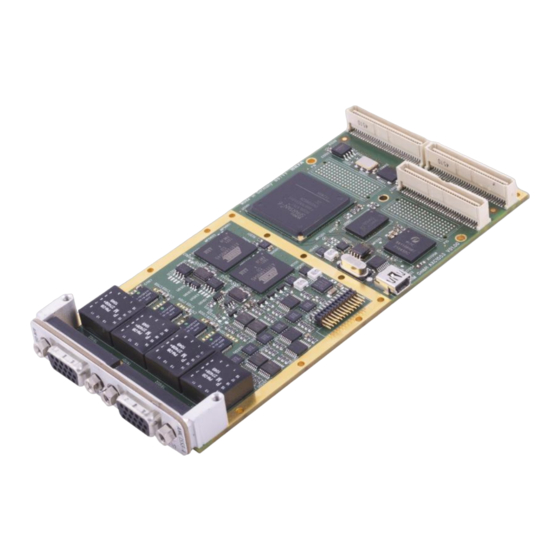
Page 12: Figure 2.1: Installing An Air Cooled Amcx1553-N Mezzanine Module
Remove the carrier board from the system slot. Place the AMCX1553-n-CC mezzanine module on top of the carrier board, with the PMC connectors on the AMCX1553-n-CC aligned with the corresponding connectors on the carrier board (see Figure 2-2). Verify the correct size of the voltage keying pins if used. -
Page 13: Connecting To Other Devices
Figure 2.2: Installing a Conduction Cooled AMCX1553-n-CC Mezzanine Module 2.3 Connecting to other Devices The external interface of the AMCX1553-4 consists of up to four dual redundant MIL-STD- 1553A/B channels, Trigger In/Out signals for Bus Monitor, Bus Controller and Remote Terminals, as well as the IRIG IN/OUT interface for multi-channel time tag synchronization. -
Page 14: Mil-Std-1553-A/B Dual Channel Interface Connector
On the AMCX1553-1/2/4 mezzanine card all MILbus signals are provided on one (AMCX1553- 1/2) or two (AMCX1553-4) female 15 pol. DSUB connector at the front panel-bezel of the mezzanine card. The pin assignment of the MILbus connector is shown in the followed tables. -
Page 15: Milbus Coupling Modes
2.3.3 Trigger and IRIG connector On the AMCX1553-n mezzanine card the Trigger and IRIG connector is implemented on each 15 pol. female, 3 row high density DSUB connector (similar to VGA standard). The connector comprises all the trigger input and output signals for both MILbus channels as well as the IRIG- B input and output signals (only on connector 1). -
Page 16: Amcx1553-N Rear-Io Interface
Installation 2.3.5 AMCX1553-n Rear-IO Interface Instead of using the front panel interface connectors (15 pol. female DSUB Connector), a full compatible Rear-IO interface may be used. All Rear-I/O Signals are available at P14 of the PMC Interface connectors. The pinout table for P14 is given on the table 2-3. -
Page 17: Structure Of The Amcx1553-N
Structure of the AMCX1553-n STRUCTURE OF THE AMCX1553-N The structure of the AMCX1553 mezzanine card is shown in the block diagram on the next page. The AMCX1553-n comprises the following main sections: PCI bus and BIU-IO FPGA Global RAM ... -
Page 18: Figure 3.1: Block Diagram Of Amcx1553-N
Structure of the AMCX1553-n Figure 3.1: Block Diagram of AMCX1553-n AMCX1553 Hardware Manual... -
Page 19: Pci Bus And Biu-I/O Fpga
Structure of the AMCX1553-n 3.1 PCI bus and BIU-I/O FPGA The common FPGA architecture of AIM’s family of PCI Express based Mezzanine modules includes both the complete PCI Express bus logic and the BIU processor logic. The PCI Express interface connects to a transparent PCIe-to-PCI bridge which realizes a 32-bit and 66MHz capable PCI upstream port. -
Page 20: Dma Engine
FPGA. 3.8 Physical Bus Interface MIL-STD-1553 Board The AMCX1553-4 contains up to four dual redundant MIL-STD-1553A/B channels. The used MILbus Transceivers provides a fixed output amplitude. The MILbus Transformers offers the following coupling modes, which may be adjusted by assembly configuration. -
Page 21: External Trigger Inputs And Outputs
(ESD sparks). Note that the Rear IO connector has no extra ESD protection and when using the conduction cooled AMCX1553-n-CC variant the ESD protection must be ensure by the Rear IO transition module placed in the carrier board. -
Page 22: Figure 3.3: Trigger Out Of Amcx1553-N
Structure of the AMCX1553-n Rear-IO PMC P14 FPGA Trig OUT-Reg BC Trigger OUT TO_BC RT Trigger OUT TO_RT TO_BM BM Trigger OUT ≥ 1 Figure 3.3: Trigger Out of AMCX1553-n AMCX1553 Hardware Manual... -
Page 23: User Programmable Discrete I/O (Gpio)
Structure of the AMCX1553-n 3.12 User programmable Discrete I/O (GPIO) The AMCX1553-n module provides eight user definable discrete I/O signals. Discrete input signals are always active whereas the discrete output signals are per default inactive. An open collector circuitry is used for the discrete output with approximately 4V provided by default. An external voltage from 0 to 35V can be supplied externally for switching higher voltages. -
Page 24: Figure 3.5: Gpio Protection With External Resistor
Structure of the AMCX1553-n Off-Board User Voltage serial Customized Discrete Output Discrete IO-Pin Front Connector FPGA Output AMCX1553-n Board Figure 3.5: GPIO Protection with external resistor AMCX1553 Hardware Manual... -
Page 25: Irig- And Time Code Section
The generated time code signal is an IRIG B compatible signal. The time code information can be used for time-tagging and multi-channel synchronization. On the AMCX1553-n a new generation of the IRIG section is implemented with a free wheeling IRIG functionality. If no external IRIG signal is detected, the TCP switches automatically to the free wheeling operation mode. -
Page 26: Voltage Supplies
Structure of the AMCX1553-n 3.14 Voltage Supplies The required voltages are provided by standard voltage supplies and especially on-board single low voltage switching power supplies. 3.14.1 Standard Voltage Supply The following voltages are used on the PMC module. They might be provided by a standard PC power supply. -
Page 27: Technical Data
Bit count error on selected word +/- 3 bits Decoder: For each BIU, one Manchester Decoder with Parity checker and error detection. Single implementation with bus switching logic (not redundant). Full error detection and indication Interword gap timer with 250ns resolution (nine bit). AMCX1553 Hardware Manual... - Page 28 The physical I/O Interface comprises a one/two dual redundant MIL- MIL-STD-1553: STD-1553 stream. It consists of the MIL-STD-1553B transceiver and a respective transformer. The output voltage of the transceiver is fixed Two Bus coupling modes (transformer and direct coupling) are provided on the connector AMCX1553 Hardware Manual...
- Page 29 Otherwise the transistor can be damaged (Paragraph 3.12). Dimensions: Single width AMCX1553-n: 149.0mm x 74.0mm Conduction cooled AMCX1553-n-CC as per ANSI/VITA 20-2001 (R2005): 143.75mm x 74.0mm Weight: AMCX1553-4 appr. 100g AMCX1553-4-CC appr. 70g Standard PC –...
- Page 30 Working means: all channels transmitting at 100% Bus load, Transformer coupled, 70Ohm Termination, MILBus output Voltage Temperature: 0 to +70°C Standard Operating -40 to +85°C Extended Temperature -40 to +85°C Storage Temperature Humidity: 0% to 95% non-condensing Conformal Coating available on Request AMCX1553 Hardware Manual...
-
Page 31: Notes
Surface Mounted Device SRAM Static Random Access Memory SSRAM Synchronous Static Random Access Memory SDRAM Synchronous Dynamic RAM Software Test Access Port (for JTAG) Time Code Processor UART Universal Asynchronous Receiver and Transmitter PCI Express Mezzanine Card AMCX1553 Hardware Manual... - Page 32 Notes THIS PAGE IS INTENTIONALLY LEFT BLANK AMCX1553 Hardware Manual...
-
Page 33: Certificate Of Volatility
All operating Data for handling the I/O Protocol will be stored in volatile memory only. No Transfer data is stored in Non-Volatile Memory. The Non-Volatile Memory only contains production relevant data for board personalisation, FPGA Logic or Firmware Code for the on board Microcontroller. AMCX1553 Hardware Manual...
Need help?
Do you have a question about the AMCX1553 and is the answer not in the manual?
Questions and answers