Table of Contents
Advertisement
Advertisement
Table of Contents

Subscribe to Our Youtube Channel
Related Manuals for BEHA Unitest TELARIS 0100 plus


Summary of Contents for BEHA Unitest TELARIS 0100 plus
- Page 1 ® UNITEST Instruction Manual Cat.-No. 9073 TELARIS 0100 plus...
-
Page 3: Table Of Contents
Content ......................Page Introduction ....................4 Model and Type ..................4 Product description ..................4 Transport and Storage ................5 Safety Measures ..................5 Appropriate Usage ..................6 Display and Control Elements ..............7 Display ......................7 Operation Elements ..................8 Carrying out Measurements..............9 Voltage Measurement ................10 Low-Ohm Resistance Measurement ............11 Insulation Measurement ................13 Mains Internal Resistance Measurement / SCC Measurement ....15 Loop Impedance Measurement / PSCCurrent Measurement ....18... -
Page 4: Introduction
Conformity symbol, the instrument complies 1.2 Product description with the valid directives. It complies with the The UNITEST TELARIS 0100 plus is a handy test and EMC Directive (89/336/EEC), Standards EN measurement instrument for testing in systems and 50081 and EN 50082-1 are fulfilled. It also installations in compliance with DIN VDE. -
Page 5: Transport And Storage
• Integrated memory for approx. 500 measurement 3.0 Safety Measures values The UNITEST Telaris 0100 plus has been designed • Standard, built-in IR RS-232 interface for trans- and checked in accordance with the safety regula- ferring measurement data to the PC tions for Electronic test and Measurement Instru- •... -
Page 6: Appropriate Usage
Safety Measures 3.1 Appropriate Usage In order to avoid electrical shock, the valid safe- ty and VDE regulations regarding excessive The instrument may only be used under those contact voltages must receive the utmost at- conditions and for those purposes for which it tention when working with voltages exceeding was built. -
Page 7: Display And Control Elements
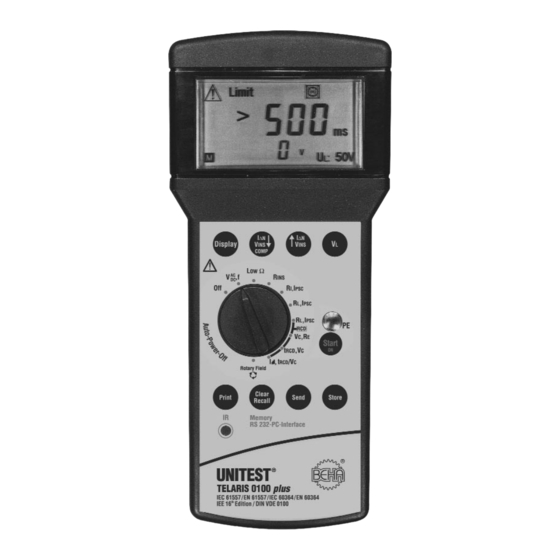
Display and Control Elements 4.0 Display and Control Elements 4.1 Display (see also chapter 7.0) 15) Current factor display for I∆N when perfor- Attention, warning symbol ming RCD checks AC voltage / DC voltage 16) Small result field shows pre-selected I∆N Exceeding the threshold when performing RCD checks Exceeding the Contact voltage threshold... -
Page 8: Operation Elements
Operation Elements 26) Start key 4.2 Operation Elements 27) Store key 21) Display key to select individual measurement 28) Send key results 29) Clear key 22) V , I∆N key: select one lower insulation test 30) IR-RS232 PC interface voltage or I∆N. LowΩ: start / switch off com- 31) Print key pensation. -
Page 9: Carrying Out Measurements
Carrying out Measurements 33) Connection Socket L - L1 Acoustic Signals 34) Connection Socket N - L2 35) Connection Socket PE - L3 Confirmation Signal: The confirmation signal is a short beep which is au- dible once an important procedure is started (e.g. start of measurement, data memorisation or delet- ing) Error Signal:... -
Page 10: Voltage Measurement
Voltage Measurement 5.1 Voltage Measurement AC voltage is displayed in the large result field (12), frequency in the small result field (14). Never apply voltages exceeding 440V AC/DC to input sockets. If voltage exceeds 440V, „>440V" is displayed in the large result field. Should this occur dis- The instrument is equipped with an integrated connect the test instrument from the EUT im- internal over voltage protection up to maxi-... -
Page 11: Low-Ohm Resistance Measurement
Low-Ohm Resistance Measurement 5.2 Low-Ohm Resistance Measurement The measurement results can be falsified by This measurement is used to check protective earth parallel connection of impedances of additio- conductors, grounding conductors, and equipoten- nal service circuits or by compensating cur- tial bonding conductors for low-impedance conti- rents. - Page 12 Compensating Test Lead Resistance 5.2.1 Compensating Test Lead Resistance TELARIS 0100 plus allows for compensation of test lead resistance. The test lead resistance may amount up to 1,99Ω. Proceed as follows: Connect 2 test leads to the TELARIS 0100 plus (sockets L1 and L2).
-
Page 13: Insulation Measurement
Insulation Measurement 5.3 Insulation Measurement For electrical installations the insulation measure- ment has to be carried out prior to final commis- sioning. This measurement is of basic importance as the insulation measurement is considered to be the only measurement for fire protection. If, due to an insulation error, a limited fault current flows be- tween two conductors, this leads to a heating up or even to a fire. - Page 14 (approx. 10s), then the UUT has a high capaci- rement voltage charges capacitive UUTs. The tance value. In this case, you should carry out UNITEST TELARIS 0100 plus automatically di- a continuous measurement, as the automatic scharges the UUT after completion of the me- measurement should be interrupted after 10s.
-
Page 15: Mains Internal Resistance Measurement / Scc Measurement
Mains Internal Resistance Measurement / Short Circuit Current Measurement Terms: 5.4 Mains Internal Resistance Measurement / Short Circuit Current Measurement Loop Impedance (ZL): Sum of impedance values within a current loop (bet- The mains internal resistance is determined by ap- ween the L and PE conductor). - Page 16 Mains Internal Resistance Measurement / Short Circuit Current Measurement Plug the plug into the socket under test. The socket is continuously checked for faults. If the "turn plug by 180°” symbol (7) is di- splayed on the screen, you are advised to eit- her turn the Schuko-plug or the exchange the L and N connectors at the instrument.
- Page 17 Mains Internal Resistance Measurement / Short Circuit Current Measurement If the resistance measured exceeds 1999 Ω, If you wish to store the condition of a faulty the attention symbol (1) and '>1999 Ω' are di- socket, please press the "Start” key (26) first. splayed on the screen.
-
Page 18: Loop Impedance Measurement / Psccurrent Measurement
Loop Impedance Measurement / Prospektive Short-Circuit Current Measurement Connect the mains to the socket plug by re- 5.5 Loop Impedance Measurement / specting the correct polarity. Prospective Short-Circuit Current Select measurement range („ZL, IPSC") by Measurement means of the measurement range selection The loop impedance (L-PE / loop impedance) is un- switch (32). - Page 19 Loop Impedance Measurement / Prospektive Short-Circuit Current Measurement If symbol „turn plug by 180°" (7) appears, turn The short-circuit current is calculated using the the mains plug by 180° and connect to the mains voltage and the loop resistance. For this, socket or exchange the N and L connectors at the value 230V is used as mains voltage if the the test instrument.
-
Page 20: Loop Impedance Measurement Without Rcd Tripping
Loop Impedance Measurement without RCD Tripping Plug the Schuko-plug into the socket under test. 5.6 Loop Impedance Measurement without RCD Tripping Select measurement range („ZL, IPSC/RCD") by means of the measurement range selection This measurement us used for loop measurement switch (32). -
Page 21: General Information About Rcd Tests
General Information about RCD Tests Read the measurement result displayed on the 5.7 General Information about RCD Tests screen. The loop resistance is displayed in the The contact voltage UB and the trip time t required large result field (12). The short-circuit current by the RCD to disconnect the subsequent current Ik is displayed in the small result field (14). -
Page 22: Rcd - Measurement Of Contact Voltage Ub And The Earthing Resistance Re Without Rcd Tripping
The instrument UNITEST TELARIS 0100 plus offers stem. An available voltage of the N conductor the facility to test contact voltage or the earthing re- to the earth can influence the measurement. - Page 23 RCD – Measurement of Contact Voltage UB Plug the Schuko-plug into the socket under test. Prior to performing the measurement, check the connection of the neutral conductor bet- Select the contact voltage measurement func- ween the mains neutral point and the earth. tion (UB/RE [RCD/FI] ) by means of the rotary dial (32).
-
Page 24: Rcd Trip Time Test, Contact Voltage (Ta, Vb / Re)
RCD Trip Time Test, Contact Voltage (ta, UB / RE) The measurement may only be started if the If you wish to store the condition of a faulty socket is not faulty and the measurement adap- socket, please press the "Start” key (26) first. ter has been connected by respecting correct After hearing the "Error Signal”... - Page 25 RCD Trip Time Test, Contact Voltage (ta, UB / RE) If the symbol for socket error (6) is displayed on the screen, we are dealing with a socket wi- ring error. If a voltage exceeding the preselec- ted contact voltage limit is present between N and PE, 'UB>UL' (4) is displayed on the screen To perform a complete socket test, touch the contact electrode PE (25) and observe the di-...
- Page 26 RCD Trip Time Test, Contact Voltage (ta, UB / RE) If the contact voltage measured exceeds the Failure for RCD tripping could be a wrong set- 50V or 100V measurement range, the attention ting of the nominal current or a faulty RCD. symbol (1) and '>50V' or '>100V' are display- ed on the screen.
-
Page 27: Rcd Test With Rising Residual Current, Trip Current
RCD Test with Rising Residual Current (Ramp Method), Trip Current (I , ta/VC 5.7.3 RCD Test with Rising Residual Current (Ramp Method), Trip Current , ta/VC For this test, the trip current I of the RCD is meas- ured. The contact voltage VC is measured during the preliminary test at a current of 1/3 I∆N. - Page 28 RCD Test with Rising Residual Current (Ramp Method), Trip Current (I , ta/VC If the trip time tA measured is not within the ad- You are dealing with a PE error, if the error sig- missible range (tA: < 300ms; 50% I∆N ? IR nal is audible and the 'Attention' symbol (1), ∆100% I∆N), the 'Attention' symbol (1) is di- and 'Socket Error' (6) are displayed.
-
Page 29: Rotary Field Test
Rotary Field Test 5.8 Rotary Field Test The UNITEST Telaris 0100 plus allows to check the rotary field within systems of nominal user voltages of approx. approx. 100 to 440V. Connect the test leads supplied with the Telaris 0100 plus, by inserting the measurement plugs labelled L1, L2, L3 into the respective sockets L1 (33) ,L2 (34), and L3 (35). -
Page 30: Storing, Printing And Data Transfer
Under certain unfavourable conditions, data may be lost or modified with any electronic memory. The company CH. BEHA GmbH will not be held responsible, neither for financial nor for any other losses caused by data loss, incorrect handling, or any other reason. -
Page 31: Viewing Measurement Data
Printing Measurement Data To print all memorised data, press the "Print" key 6.3 Printing Measurement Data (31) for a longer time (approx. 3 seconds). "Prt” Saving after the measurement result, it is possible is displayed on the screen, The data is trans- to print the datas. -
Page 32: Printing Measurement Data
Deleting Saved Measurement Data/View the Memory Location Number 6.4 Deleting Saved Measurement 6.6 Infrared Interface, send Measurement Data Data/View the Memory Location Number Additionally, all stored measurement data may be transferred to the PC (for reporting) by the Infrared It is possible to delete the last measurement value Interface. -
Page 33: Displays / Error Messages
Displays / Error Messages 7.0 Displays / Error Messages Functions Message Cause Attention symbol for exceeding limit values Batteries are virtually empty and have to be replaced. Measurement results no longer comply with the specifications. Batteries are empty. No function of the Telaris is blinking Minimum one measurement result has been stored in memory. - Page 34 Displays / Error Messages Function Message Cause Rs, IPSC RI, IPSC Loop impedance is higher than 1999 Ohm Rs, IPSC RI, IPSC Contact voltage has exceeded preset limit during the socket test. Measurement therefore not carried out, until instrument has been allowed to cool down.
- Page 35 Displays / Error Messages Function Message Cause Selective RCD has tripped at 219 ms. As trip time exceeds 200ms, the RCD has failled! RCD has tripped at 345 ms. As trip time exceeds 300ms, the RCD has failled! The contact voltage exceeded the pre-set limit Measurement therefore not carried out The contact voltage exceeded the pre-set limit, more than 100 V.
-
Page 36: Energy Management
Energy Management /Maintenance/Battery Replacement 8.0 Energy Management 10.0 Battery Replacement Approximately 5 minutes after the last key operation, If the battery symbol (8) appears in the display, pro- the instrument switches off automatically (auto- ceed with battery replacement. power-off). To switch the instrument on again, turn the rotary switch from the „OFF"... - Page 37 Battery Replacement Switch off the instrument via the rotary switch and disconnect the instrument from the connected measurement circuits. Remove holster Loosen the screws on the rear of the instrument Lift the battery case cover (by gently hitting the in- strument in the palm of your hand).
-
Page 38: Built In Fuses
Built in fuses 11.0 Built in fuses For the function RI, IPSC - Internal Line Resistance The instrument measurement inputs are protected Display >1999Ohm also for sockets, which pos- by fuses, described in Section 13, Technical Data. sess a known low internal resistance (other elec- trical loads do function): Fuse F1 has tripped. -
Page 39: Technical Data
Technical Data 13.0 Technical Data General technical data: Display: digit or 3 digit LCD Reference-Range: +17°C to 27°C, max. 70% rel. humidity Temperature-Range: 0°C to 40°C, relative humidity max. 80% Storage temperature: -10°C...+60°C Height above MSL: up to 2000m Battery type: 6x 1,5V Mignon Typ IEC LR6 (size AA) Current-consumption: 20mA (Stand-by) - Page 40 Technical Data Insulation Measurement Rins: Measurement Range: 0,05 ... 19,99 MΩ, 20,0 ... 199,9 MΩ Resolution: 0,01 MΩ, 0,1 MΩ Tolerance: ±(5% rdg. + 5 Digit) Nominal- Max. open-circuit Numbers of measurement with 1mA output voltage voltage Uq Load (1 Measurement - 25s break) 100V DC UN + 50% approx.
- Page 41 Technical Data Loop Impedance Z 230 V +10 % -15 % (50...60 Hz), cos ϕ 0,95 Mains nominal voltag: 0,15 ... 19,99 Ω, 20,0 ... 199,9 Ω, 200 ... 1999 Ω Measurement Range: 0,05 Ω...1999 Ω Display Range: 0,01 Ω, 0,1 Ω, 1 Ω Resolution: Tolerance: ±(6% rdg.
- Page 42 Technical Data RCD-Test: Nominal Voltage: 230 V, +10 % -15 %, (50...60 Hz) Measurement time: approx. 2s, approx. 31s (selektive RCD/FI), max. 18s (measurement of trip current) Current switch-off: immediately at RCD tripping or at true excess of contact voltage limit. The protective conductor must be free of noise voltage.
-
Page 43: Month Warranty
Any damage due to dropping or incorrect handling are not covered by the warranty. If the instrument shows failure following expiration of warranty, our service department can offer you a quick and economical repair. ® CH. BEHA GmbH Elektronik - Elektrotechnik In den Engematten 14 79286 Glottertal / Germany Tel.: +49 (0) 76 84/ 80 09-0... - Page 44 Certificat de Qualité • Certificado de calidad Die BEHA-Gruppe bestätigt The BEHA Group confirms Le groupe BEHA déclare que El grupo BEHA declara que el hiermit, dass das erworbene herein that the unit you have l´appareil auquel ce document producto adquirido ha sido ca- Produkt gemäß...
Need help?
Do you have a question about the Unitest TELARIS 0100 plus and is the answer not in the manual?
Questions and answers