Table of Contents
Advertisement
Available languages
Available languages
Quick Links
Advertisement
Chapters
Table of Contents

Subscribe to Our Youtube Channel
Related Manuals for BEHA UNITEST CHB5


Summary of Contents for BEHA UNITEST CHB5
- Page 1 CHB 5 Leckstromzange 93570 • Bedienungsanleitung • Instruction Manual...
-
Page 3: Table Of Contents
Inhaltsverzeichnis ................Seite Auf dem Gerät und in der Bedienungsanleitung vermerkte Hinweise:..2 Einleitung / Lieferumfang ............3 Transport und Lagerung ............3 Sicherheitsmaßnahmen ............4 Bedienelemente und Anschlüsse..........5 Durchführung von Messungen ..........6 Vorbereitung und Sicherheitsmaßnahmen ........6 Batterien einlegen: ..............6 Durchführen von Strommessungen ..........7 Durchführen von Leckstrommessungen ........8 Durchführen von Spannungsmessungen ........9 Oberschwingungen/Oberwellen Messung Absolutwert (in mA/A/V) oder Prozentanteil ......10... -
Page 4: Auf Dem Gerät Und In Der Bedienungsanleitung Vermerkte Hinweise
Auf dem Gerät und in der Bedienungsanleitung vermerkte Hinweise: Warnung vor einer Gefahrenstelle. Bedienungsanleitung beachten. Hinweis. Bitte unbedingt beachten. Vorsicht! Gefährliche Spannung, Gefahr des elektrischen Schlages. Achtung! Zugelassen zum einsetzen um oder zum entfernen von gefährlichen aktiven Leitungen (z.B. Stromschienen). Kennzeichnung elektrischer und elektronischer Geräte (WEEE Richtlinie 2002/96/EG). -
Page 5: Einleitung / Lieferumfang
Einleitung / Lieferumfang Die UNITEST Stromzange CHB 5 ist ein universell einsetzbares Instrument. Das Messgerät wird nach den Normen gebaut und gewährleistet ein sicheres und zuver- lässiges Arbeiten. Die Stromzange ist im handwerklichen und industriellen Bereich eine wertvolle Hilfe. Durch die sehr hohe Empfindlichkeit des Strombereiches, kann der Ableitstrom (Leckstrom) eines Verbrauchers gemessen werden. -
Page 6: Sicherheitsmaßnahmen
Sicherheitsmaßnahmen Die UNITEST Stromzange CHB 5 wurde gemäß den Sicherheitsbestimmungen IEC 1010, EN 61010 für elektronische Messgeräte gebaut, geprüft und hat das Werk in sicherheitstechnisch einwand-freiem Zustand verlassen. Um diesen Zustand zu er- halten, muss der Anwender die Sicherheitshinweise in dieser Anleitung beachten. Um einen elektrischen Schlag zu vermeiden, sind Vorsichtsmaßnahmen zu beachten, wenn mit Spannungen größer 120 V (60 V) DC oder 50 V (25 V) eff AC gearbeitet wird. -
Page 7: Bedienelemente Und Anschlüsse
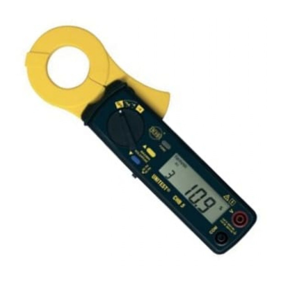
Bedienelemente und Anschlüsse 1.) Messwertaufnehmer (Stromzange) 2.) Zangenöffnungshebel 3.) Messart-Wahlschalter mit EIN/AUS-Schalter, ~mA, ~A und ~V. - Taste zur Auswahl von MAX/MIN, HOLD und PEAK bzw. zur Auswahl der einzelnen harmonischen Oberwellen (1...99, rückwärts). - Taste zum Beenden von MAX/MIN, HOLD und PEAK bzw. zur Auswahl der einzelnen harmonischen Oberwellen (1...99, vorwärts). -
Page 8: Durchführung Von Messungen
Durchführung von Messungen Vorbereitung und Sicherheitsmaßnahmen Batterien einlegen: Bevor das Gerät in Betrieb genommen wird, müssen die Batterien eingelegt werden. Dazu wird folgendermaßen vorgegangen. 1) Das Gerät muss vom Messkreis getrennt und alle Messleitungen entfernt werden. 2) Das Gehäuse wird geöffnet, indem die Schraube auf der Rückseite des Gerätes gelöst wird und der Batteriefachdeckel in Pfeilrichtung gezogen wird. -
Page 9: Durchführen Von Strommessungen
Durchführen von Strommessungen Vor dem Umschalten auf eine neue Funktion oder einen anderen Messbereich ist die Zange stets vom Prüfobjekt zu entfernen. 1) Den Messart-Wahlschalter (3) entsprechend dem zu erwartenden Strom auf Stellung "~mA oder ~A" stellen. 2) Gewünschte Grundfrequenz mit Umschalter (10) auswählen. 3) Stromzange öffnen und den Stromleiter umschließen. -
Page 10: Durchführen Von Leckstrommessungen
Durchführen von Leckstrommessungen Vor dem Umschalten auf eine neue Funktion oder einen anderen Messbereich ist die Zange stets vom Prüfobjekt zu entfernen. 1) Den Messart-Wahlschalter (3) entsprechend dem zu erwartenden Strom auf Stellung "~mA oder ~A" stellen. 2) Gewünschte Grundfrequenz mit Umschalter (10) auswählen. 3) Stromzange öffnen und den Stromleiter umschließen. -
Page 11: Durchführen Von Spannungsmessungen
Durchführen von Spannungsmessungen Es dürfen nicht mehr als 600 V AC/DC an den Eingangsbuchsen angelegt wer- den. Bei Überschreiten dieser Grenzwerte droht eine Beschädigung des Ge- rätes und eine Gefährdung des Bedieners. Vor dem Umschalten auf eine neue Funktion oder einen anderen Messbereich sind die Messleitungen stets vom Prüfobjekt zu entfernen. -
Page 12: Oberschwingungen/Oberwellen Messung Absolutwert (In Ma/A/V) Oder Prozentanteil
Oberschwingungen/Oberwellen Messung Absolutwert (in mA/A/V) oder Prozentanteil 1) Den Messart-Wahlschalter (3) auf "~mA, ~A oder ~V" stellen. 2) Gewünschte Grundfrequenz mit Umschalter (10) auswählen. 3) Messfunktion ”Harmonic” oder ”Hamronic + %”mittels der Taste FUNC (6) be- stimmen. Die harmonischen Oberwellen (1... 99) können Sie mit Hilfe der Tasten oder (5) ansehen. -
Page 13: Scheitelfaktormessung (Crest-Factor)
Scheitelfaktormessung (Crest-Factor) 1) Den Messart-Wahlschalter (3) auf "~mA, ~A oder ~V" stellen. 2) Gewünschte Frequenz mit Umschalter (10) einstellen. 3) Messfunktion ”C.F.” mittels der Taste FUNC (6) bestimmen. 4) bei ~mA und A Messung 1) Stromzange öffnen und den Stromleiter umschließen. Es ist darauf zu ach- ten, dass die Zange den Stromleiter vollständig umschließt und kein Luft- spalt vorhanden ist. -
Page 14: Min/Max-Messung
MIN/MAX-Messung Mit der Taste MIN/MAX kann wahlweise der größte bzw. der kleinste Wert einer Meß- reihe erfaßt werden. Das Drücken der MIN/MAX-Taste aktiviert den MIN-Modus, d.h. der kleinste Wert wird erfaßt. Durch ein weiteres Drücken der Taste wird der MAX- Modus eingeschaltet, d.h. -
Page 15: Kalibrierintervall
Bitte an dieser Stelle auch an unsere Umwelt denken. Verbrauchte Batterien nicht in den normalen Hausmüll werfen, sondern die Batterien bei Sonder- mülldeponien oder Sondermüllsammlungen abgeben. Es müssen die jeweils gültigen Bestimmungen bzgl. der Rücknahme, Ver- wertung und Beseitigung von gebrauchten Batterien beachtet werden. Wird das Gerät über einen längeren Zeitraum nicht benutzt, müssen die Bat- terien entnommen werden. -
Page 16: Technische Daten
Technische Daten (bei 23° C % 5° C, max. 75 % rel. Feuchte) Anzeige: 4+2+2 (??) stellige, digitale LC-Anzeige mit Anzeige der Funk- tionen und Symbole Bereichswahl: automatisch Auto-Power-Off: ca. 30 min. Nach dem Abschalten kann die Zange nach ca. 10 Sekunden wieder eingeschaltet werden. - Page 17 Oberwellenmessung in mA, A (Absolutwert) Spezifiziert ab 100mA 50/60Hz (mA Messbereich) oder ab 1A 50/60Hz (A Messbereich) Messbereich Auflösung Genauigkeit 1...10 ± 1 % v.M. ± 1 mA 11...20 0,01 mA / 0,1 mA ± 5 % v.M. ± 1 mA 21...50 0,001 A / 0,01 A ±...
-
Page 18: 24 Monate Garantie
Spitzenwert (PEAK Value) im mA, A und V Messbereich Spezifiziert ab 10mA (mA Messbereich) oder ab 0,5A (A Messbereich) oder ab 5 V AC (V Messbereich) Messbereich Abtastrate (Zeit) Genauigkeit 50 Hz 39 µs ± 5 % v.M. ± 30 D 60 Hz 33 µs Wechselstrom Scheitelfaktor (Crest Factor) - Page 19 Content ..................Page References marked on instrument or in instruction manual: ....2 Introduction / Scope of Supply ..........3 Transport and Storage ..............3 Safety ..................4 Controls and Connections............5 Operation ..................6 Preparation and safety measures ..........6 Inserting the batteries ..............6 Current Measurements ..............7 Leakage Current Measurement ..........8 Voltage Measurement ..............9 Harmonics of AC Current in Magnitude (mA or A)
-
Page 20: References Marked On Instrument Or In Instruction Manual
References marked on instrument or in instruction manual: Warning of a potential danger, comply with instruction manual. Reference. Please use utmost attention. Caution! Dangerous voltage. Danger of electrical shock. Caution! Application around and removal from HAZARDOUS LIVE conduc- tors is permitted. Symbol for the marking of electrical and electronic equipment (WEEE Direc- tive 2002/96/EC). -
Page 21: Introduction / Scope Of Supply
Introduction / Scope of Supply The UNITEST CHB 5 is a universal, multi-purpose electrical measuring instrument. It comply with the standards DIN VDE 0411 and EN 61010, and provide safe, reli- able operation. The clamp meter is a valuable tool for all sorts of measurements in both trade and industry. -
Page 22: Safety
Safety The UNITEST Clamp Meter CHB 5 has been manufactured and tested to comply with the safety regulations for electronic measuring equipment contained in DIN VDE 0411 and EN 61010, and left our works in a safe condition.To maintain this con- dition, the user must observe the safety instructions contained in this Instruction Manual. -
Page 23: Controls And Connections
Controls and Connections 1.) Induction coil (clamp) 2.) Clamp Openenr (hand gear) 3.) Selector switch, for type of measurement ON/OFF-Switxh, ~mA, ~A and ~V. - key to select MAX/MIN, HOLD and PEAK or to select single harmonics (1..99, backward). - key to stop MAX/MIN, HOLD and PEAK or to select single harmonics (1..99, forward). -
Page 24: Operation
Operation Preparation and safety measures Fitting the battery Before using the instrument, the battery must be fitted. This is carried out as fol- lows: 1) Separate the instrument from any circuit, and remove the test leads. 2) Open the housing by removing the screw on the rear face. 3) Fit a new battery (1,5 V IEC LR6), taking care that the polarity is correct. -
Page 25: Current Measurements
Current Measurements Before switching to a new function, the probes must always be removed from the UUT. 1) Turn selector switch (3) to the current range (mA or A) you need 2) Select basic frequency via switch(10). 3) Open the clamp, and close it round the conductor. Make sure that the clamp properly encircles the conductor, and that there is no air gap between the jaws. -
Page 26: Leakage Current Measurement
Leakage Current Measurement Before switching to a new function, the probes must always be removed from the UUT. 1) Turn selector switch (3) to the current range (mA or A) you need 2) Select basic frequency via switch(10). 3) Open the clamp, and close it round the conductor. Make sure that the clamp properly encircles the conductor, and that there is no air gap between the jaws. -
Page 27: Voltage Measurement
Voltage Measurement Do not connect more than 600 V AC / DC to the input sockets. Exceeding these values can endanger the operator, and may result in damage to the in- strument. Before switching to a new function, disconnect the probes from the UUT. Only handle test leads and probes on the grips provided. -
Page 28: Harmonics Of Ac Current In Magnitude (Ma Or A) Or In Percentage (%)
Harmonics of AC Current in Magnitude (mA or A) or in Percentage (%) 1) Turn selector switch (3) to "~mA, ~A oder ~V" 2) Select basic frequency via switch(10). 3) Select ”Harmonic” or ”Harmonic +%” vie key FUNC (6) Press the button to increment or decrement the order of harmonics in front of the reading. -
Page 29: Crest Factor (C.f.)
Crest Factor (C.F.) 1) Turn selector switch (3) to "~mA, ~A oder ~V" 2) Select basic frequency via switch(10). 3) Select ”C.F.” vie key FUNC (6) 4) at ~mA and A measurement 1) Open the clamp, and close it round the conductor. Make sure that the clamp properly encircles the conductor, and that there is no air gap between the jaws. -
Page 30: Min/Max Measurement
MIN/MAX Measurement The MIN/MAX button can be used to find either the largest or the smallest value of a series of measurements. Pressing the MIN/MAX button activates first the MIN mode, so that the smallest value is selected. Pressing it a second time changes to MAX mode, for the largest value. -
Page 31: Calibration Interval
Please consider your environment when you dispose of your one-way batte- ries or accumulators. They belong in a rubbish dump for hazardous waste. In most cases, the batteries can be returned to their point of sale. Please, comply with the respective valid regulation regarding the return, re- cycling and disposal of used batteries. -
Page 32: Technical Data
Technical Data (at 23° C % 5° C, max. 75 % rel. humidity) Display: 4+2+2, LCD incl. functions and symbols Range Selection: automatic Auto-Power-Off: approx. 30 min. Overload display: Measuring rate: 2 measurements/sec. (LCD) Clamp opening: ca. 30 mm (1/2 inch) Overvoltage Categorie: CAT II, 600 V / CAT III, 300 V Pollution degree:... - Page 33 Harmonics in mA, A (Absolutwert) Spezifiziert ab 100mA 50/60Hz (mA Range) oder ab 1A 50/60Hz (A Range) Range Resolution Accuracy 1...10 ± 1 % rdg. ± 1 mA 11...20 0,01 mA / 0,1 mA ± 5 % rdg. ± 1 mA 21...50 0,001 A / 0,01 A ±...
-
Page 34: 24 Month Warranty
Any damage due to dropping or incorrect handling are not covered by the warran- If the instrument shows failure following expiration of warranty, our service depart- ment can offer you a quick and economical repair. BEHA reserves the right to make change. - Page 35 Certificat de Qualité • Certificado de calidad Die BEHA-Gruppe bestätigt The BEHA Group confirms Le groupe BEHA déclare que El grupo BEHA declara que el hiermit, dass das erworbene herein that the unit you have l´appareil auquel ce document producto adquirido ha sido ca- Produkt gemäß...
- Page 36 R e g . N o . 3 3 3 5 06/2006 PTDB93570000-00...
Need help?
Do you have a question about the UNITEST CHB5 and is the answer not in the manual?
Questions and answers