Table of Contents
Advertisement
Quick Links
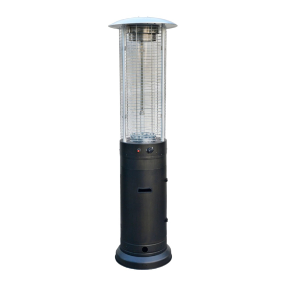
RAPID INDUCTION AREA HEATER
DANGER
INSTALLER:
Leave this manual with the appliance.
CONSUMER:
Retain this manual for future reference.
WARNING: For Outdoor Use Only.
DANGER:
IF YOU SMELL GAS:
1. Shut off gas to the appliance.
2. Extinguish any open flame.
3. If odor continues, keep away from the appliance and
immediately call your gas supplier or fire department.
DANGER:
Do not store or use gasoline or other flammable vapors
and liquids in the vicinity of this or any other appliance.
A propane cylinder not connected
for use shall not be stored in the vicinity of this or any
other appliance.
WARNING:
Improper installation, adjustment, alteration,
service or maintenance can cause property damage,
injury or death. Read the installation, operating and
maintenance instructions thoroughly before installing
or servicing this equipment.
WARNING:
FUELS USED IN LIQUEFIED
PROPANE GAS APPLIANCES,AND THE PRODUCTS
OF COMBUSTION OF SUCH FUELS, CAN EXPOSE
YOU TO CHEMICALS INCLUDING BENZENE, WHICH
IS KNOWN TO THE STATE OF CALIFORNIA TO CAUSE
CANCER AND CAUSE BIRTH DEFECTS OR OTHER
REPRODUCTIVE HARM.
For more information go to: www.P65Warnings.ca.gov.
CARBON MONOXIDE HAZARD
This appliance can produce carbon monoxide which
has no odor. Using it in an enclosed space can kill you.
Never use this appliance in an enclosed space such as
a camper, tent, car or home.
®
3
Advertisement
Table of Contents

Related Manuals for BOND MANUFACTURING RAPID INDUCTION AREA HEATER HYPH4601-12


Summary of Contents for BOND MANUFACTURING RAPID INDUCTION AREA HEATER HYPH4601-12
- Page 1 ® RAPID INDUCTION AREA HEATER INSTALLER: Leave this manual with the appliance. CONSUMER: Retain this manual for future reference. WARNING: For Outdoor Use Only. DANGER: IF YOU SMELL GAS: 1. Shut off gas to the appliance. 2. Extinguish any open flame. 3.
-
Page 2: Safety Information
SAFETY INFORMATION Before you assemble or operate this unit, please carefully read this entire manual. Failure to do so may result in a fire, explosion, injury or death. WARNINGS: 1. The installation of this unit must adhere to local codes or Propane Storage and Handling Code, CSA B149.2. 2. - Page 3 SAFETY INFORMATION 30. If the flame goes out while burning, turn the gas valve off. Wait 5 minutes before repeating the initial lighting procedure. Once you have a flame started, hold down the control knob for 1 minute. 31. Do not add water into the unit. 32.
- Page 4 SAFETY INFORMATION Only use the regulator and hose assembly provided with this unit. Replacement parts must be supplied parts by the manufacturer. Inspect the burner before use of this unit. If the burner shows any kind of damage, do not operate the appliance. For assistance with repair or replacement of the burner or any other parts, call the manufacturer at 1-877-447- 4768 NOTE: You must follow all steps to properly assemble this heating item.
- Page 5 HARDWARE PART DESCRIPTION M8 x 16 Screw M16 x 12 Screw M6 Nut M5 x 12 Screw M5 Nut Ancor Anchoring Arm Wrench M8 x 75 Stud M8 Nut M6 x 60 Stud M6 Cap Nut M6 Washer...
-
Page 6: Package Contents
PACKAGE CONTENTS PART DESCRIPTION PART DESCRIPTION Reflector Glass Tube Upper Radiation Screen Mesh Guard Lower Radiation Screen Battery (AA) Glass Tube Ring Wheel Assembly Burner Upper Supporter Tank Housing Belt... - Page 7 PREPARATION Before beginning assembly of product, make sure all parts are present. Compare parts with package contents list and hardware contents above. If any part is missing or damaged, do not attempt to assemble the product. Contact customer service for replacement parts. Estimated Assembly Time: 30 minutes Tools Required for Assembly (included): Wrench Tools Required for Assembly (not included): Philips Screwdriver...
- Page 8 ASSEMBLY INSTRUCTIONS Step 2 Attach the anchoring arms (GG) onto the base of the tank housing (F) using 6 M6 x 12 screws (BB) and 6 M6 nuts (CC). Step 3 Flip over the tank housing (F) so that it is right-side up.
- Page 9 ASSEMBLY INSTRUCTIONS Step 5 Remove the 3 preassembled M5 nuts from the upper support (K). Slide the 3 upper supports into the slots at the top of the burner (E). Once fully inserted, secure the upper supporters into the burner by reattaching the M5 nuts that were removed at the beginning of this step.
- Page 10 ASSEMBLY INSTRUCTIONS Step 8 Attach the reflector (A) to the radiation screen assembly using 3 M6x60 studs (KK), 3 M6 washers (MM) and 3 M6 cap nuts (LL). Tighten with the included wrench (HH). Step 9 Remove the 3 preassembled screws from the upper supports (K).
- Page 11 ASSEMBLY INSTRUCTIONS Step 11 Attach the 3 mesh guards (H) onto the hooks at the top of the upper supports (K). Step 12 Optional: Use the anchor (FF) to fasten the product to the ground. At the base of the unit, insert the anchors (FF) through the anchoring arms (GG) and into the ground.
-
Page 12: Operation
ASSEMBLY INSTRUCTIONS Step 14 PRESSURE Turn the cylinder valve on the tank clockwise to close RELIEF VALVE CYLINDER VALVE the propane tank. Attach the preassembled regulator to BLEED-OFF BLACK COUPLING NUT VALVE the cylinder valve by turning the regulator coupling nut turn clockwise to connect clockwise. -
Page 13: Care And Maintenance
OPERATION To Light 1. Unscrew the ignition button on the burner to see if the battery (I) has already been placed inside. If the battery (I) is not already within the ignition button on the burner, please place the battery (I) into the ignition button slot. -
Page 14: Troubleshooting
TROUBLESHOOTING Problem Possible Cause Solution Gas valve may be off Turn the gas valve on Gas tank may be empty Refill the gas tank Pilto won't Light Orifice may be blocked Clean out the orifice Air is within supply system Pump out air from all lines Loose connection Check all fittings and tighten connections as... -
Page 15: Replacement Parts List
REPLACEMENT PARTS LIST For replacement parts, call our customer service department at 1-877-447-4768, 8:00 a.m. – 4:30 p.m., CST, Monday – Friday. Or contact customerservice@ghpgroupinc.com PART DESCRIPTION Part # Reflector 30-01-661 Upper Radiation Screen 30-01-662 Lower Radiation Screen 30-01-663 Glass Tube Ring 30-01-664 Burner 30-01-665...
Need help?
Do you have a question about the RAPID INDUCTION AREA HEATER HYPH4601-12 and is the answer not in the manual?
Questions and answers