Table of Contents
Advertisement
Quick Links
Advertisement
Table of Contents

Related Manuals for Lucenti BLACKWAVE PIXLDRIVE8 PRO

Summary of Contents for Lucenti BLACKWAVE PIXLDRIVE8 PRO
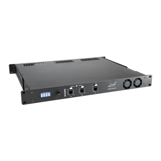
- Page 1 BLACKWAVE PIXLDRIVE8 PRO CONTROLLER QUICK START GUIDE RELEASE V1.0...
- Page 2 KLSTR enabled products using our KLSTR application. KLSTR is designed to simplify the control and configuration of lighting setups. In this quick start guide we will show you how easy and intuitive the KLSTR application is. LUCENTI LIGHTING WWW.LUCENTI.LIGHTING • INFO@LUCENTI.LIGHTING...
-
Page 3: Table Of Contents
TABLE OF CONTENTS GETTING PREPARED DOWNLOAD THE DESKTOP APP INSTALLATION WINDOWS MACOS GETTING STARTED WITH KLSTR CONNECT YOUR DEVICES ETHERNET DAISY CHAINING STAR AND RING TOPOLOGIES PIXLBUS SELECT INTERFACE NETWORK TOPOLOGY VIEW NETWORK DEVICES AND SUBDEVICES DEVICE CONFIGURATION DISCOVERY OVERVIEW PORT SPECIFIC CONTROL DEVICE MODE... -
Page 4: Getting Prepared
GETTING PREPARED Download the desktop app First of all you will need to download the KLSTR control application called KLSTR.CTRL. We are building and adding new features continuously, both on the device firmware and the application. You can download the latest version of our application on latest.KLSTR.tech. The application is available for Windows 10 and macOS. -
Page 5: Macos
macOS First, download the dmg containing the application and mount it. Drag the application to the applications folder. Go to your applications folder and open the application. When you start the KLSTR application for the first time, macOS might ask you if you want to open the application because it was downloaded from the internet. - Page 6 To fix this, open your SYSTEM PREFERENCES, go to SECURITY AND PRIVACY : Click on “Open Anyway” to start the application. GETTING PREPARED...
-
Page 7: Getting Started With Klstr
GETTING STARTED WITH KLSTR Connect your devices Ethernet Every KLSTR.one device has 3 ethernet ports, referred to as port A, B and C. KLSTR.one is built on a managed ethernet switch that allows you to connect your devices in every topology that suits you best. -
Page 8: Star And Ring Topologies
Star and Ring topologies Introducing the relay protects your ethernet based lighting system from power failure in your system, however it does not protect your setup against faulty cables, connectors that become loose or ethernet / dmx converters that malfunction. With KLSTR.one we introduce real redundancy to your lighting rig by offering the possibility to create rings in your cabling. - Page 9 In case of a change in the cabling topology, KLSTR will activate this backup path and send the data through the other path. The broken cable will be indicated with a red dotted line. Any combination of topology can be created. KLSTR will automatically configure the necessary connections to reach all devices and create all the necessary backup paths.
- Page 10 GETTING STARTED WITH KLSTR...
-
Page 11: Pixlbus
PixlBus A PixlDrive8 Pro controller sits between a power outlet and a collection of fixtures that understand the ‘PixlBus’ protocol. The PixlBus provides power and data to all connected fixtures. The following figures focus on connecting BlackWave Collection BW-100 and BW-50 bars to the controller. First connect all BlackWave pixel bars to each other. -
Page 12: Select Interface
Select interface Connect the computer to the same ethernet network where your KLSTR devices are connected to each other. When you start the KLSTR.CTRL application, you need to select the ethernet interface where your devices are connected to. In the top left side of your screen, open the KLSTR item in the menu and select SELECT INTERFACE. The pop-up window which follows, allows you to select one of your available ethernet interfaces. -
Page 13: Network Topology View
Network Topology view The Network Topology tab will draw all your KLSTR devices in the network and show you the cables that interconnect KLSTR devices. When you point your mouse over one of the cables, it will show you from which port to which port your cable runs. You can move devices on the screen to match their representation in the real world. -
Page 14: Network Devices And Subdevices
Devices) and the ones who are in need of an intermediary (Subdevices). Examples of these intermediaries are DMX Nodes, Pixel converters or controllers like the Lucenti PixlDrive8 Pro. They act as a translator, making non-networked devices available on the KLSTR network. -
Page 15: Device Configuration
DEVICE CONFIGURATION All configurations of a device can be accessed by pressing the gear symbol ( ). Click it, and the KLSTR application will open up the device configuration page. Discovery The controller features intelligent enumeration and auto-addressing of all connected fixtures through the smart PixlBus. -
Page 16: Overview
Overview The overview will now show you the devices discovered on each port. Also, it will give you an overview of the current settings. To easily identify all the devices behind a certain port, toggle the Lamp icon for the port you want to identify. -
Page 17: Port Specific
Port specific To easily identify a single device, toggle the Lamp icon for the device you want to identify. DEVICE CONFIGURATION... -
Page 18: Control
Control Device mode The controller can be switched to one of 4 different device operating modes. The controller will store and start up in the selected device mode after reboot. eDMX Slave to external Ethernet DMX (eDMX) input. The controller receives data from an external lighting controller or software. Select the protocol you want to use. -
Page 19: Effects Engine (Standalone Operation)
Effects Engine (standalone operation) The controller is equipped with a powerful internal effect engine that can dynamically generate colors and animations for all connected fixtures. Configuration options for the engine appear when the option is selected. Test patterns The controller is equipped with a set of built-in test patterns that run on all connected fixtures. A list with all available test patterns appears when the option is selected. - Page 20 SAVVY LIGHTING WWW.LUCENTI.LIGHTING • INFO@LUCENTI.LIGHTING...
Need help?
Do you have a question about the BLACKWAVE PIXLDRIVE8 PRO and is the answer not in the manual?
Questions and answers