Table of Contents
Advertisement
Quick Links
Advertisement
Table of Contents

Related Manuals for Lucenti BLACKWAVE PIXLDRIVE1

Summary of Contents for Lucenti BLACKWAVE PIXLDRIVE1
- Page 1 BLACKWAVE PIXLDRIVE1 CONTROLLER USER MANUAL...
- Page 2 This manual was produced with care. However, no rights can be derived. Lucenti cannot accept liability for any errors in this manual or their consequences. Copyright Lucenti Worldwide distribution by FACE BVBA Belgium HOEK 76 UNIT 301 –...
- Page 3 LUCENTI LIGHTING WWW.LUCENTI.LIGHTING • INFO@LUCENTI.LIGHTING...
-
Page 4: Table Of Contents
TABLE OF CONTENTS YOUR BLACKWAVE COLLECTION PIXLDRIVE1 CONTROLLER THE BLACKWAVE COLLECTION TECHNOLOGY SAFETY INSTRUCTIONS & WARRANTY SIGNS AND SYMBOLS USED USAGE INTRUCTIONS WARRANTY UNBOXING TERMS & CONCEPTS CABLING & POWERING UP CONNECTING BLACKWAVE PIXEL BARS MAXIMUM CABLING CONSIDERATIONS QUICK START GUIDE CONNECT TO CONTROLLER 7.1.1 ETHERNET... - Page 5 EFFECTS 9.3.1 OFF (LIVE INPUT) 9.3.2 EFFECT CONTROLS 9.3.3 TEST PATTERNS MISC. 9.4.1 DEVICE INFORMATION 9.4.2 FACTORY RESET 9.4.3 FIRMWARE 9.4.4 NODES INFORMATION 9.4.5 UPDATE NODE FIRMWARE HELP FAQ/TROUBLESHOOTING TECHNICAL SPECIFICATIONS...
-
Page 6: Your Blackwave Collection Pixldrive1 Controller
YOUR BLACKWAVE COLLECTION PIXLDRIVE1 CONTROLLER Thank you for purchasing a Lucenti BlackWave Collection PixlDrive1 controller! The BlackWave Collection pixel system consists of ultra-light, slim, weatherproof RGBW pixel fixtures such as led pixel bars and an easy-to-use controller. These pixel bars contain individually controllable LEDs, can be daisy chained up to 400 pixels and have a variety of interchangeable filters. -
Page 7: The Blackwave Collection Technology
THE BLACKWAVE COLLECTION TECHNOLOGY The BlackWave controller and pixel products are developed and engineered from the ground up and communicate through a custom digital bus protocol, called ‘PixlBus’. The ‘PixlBus’ protocol allows devices to communicate bi-directionally at high speeds. This enables the controller to send colors to each pixel fixture individually but also to read status or product information from each device. -
Page 8: Safety Instructions & Warranty
SAFETY INSTRUCTIONS & WARRANTY 3.1 Signs and symbols used Sign/symbol Description Indicates side information about the current subject. Indicates an important warning that needs to be read in order to be able to continue. 3.2 Usage instructions CAUTION: TO REDUCE THE RISK OF ELECTRIC SHOCK, DO NOT REMOVE THE COVER. THE DEVICE HAS NO USER SERVICEABLE PARTS INSIDE. -
Page 9: Warranty
3.3 Warranty Warranty Period - 2 (two) years This warranty can be provided when the Lucenti products were used in their normal intended use and when due care and compliance with the instructions given by Lucenti was observed. The obligations of Lucenti have been restricted to these warranty terms and conditions and the warranty does not cover losses incurred as a result of damage to other property or persons. -
Page 10: Unboxing
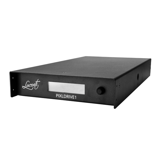
UNBOXING The PixlDrive1 controller provides both data and power to the connected fixtures through the PixlBus connector. The specifics of the controller are described in figure 2 and 3. The different components are explained in the following table. LCD Display Rotary pushbutton Figure 2: Front of PixlDrive1 controller Figure 3: Back of PixlDrive1 controller... -
Page 11: Terms & Concepts
TERMS & CONCEPTS Please carefully read the following section to understand the terminology user later on in this manual. Ethernet The controller has a built-in 100Mbit network switch exposed through connectivity two etherCON ports. These ports can receive Art-Net or sACN/E1.31 data and are also used to reach the built-in configuration webpage. -
Page 12: Cabling & Powering Up
CABLING & POWERING UP 6.1 Connecting BlackWave pixel bars A PixlDrive1 controller sits between a power outlet and a collection of fixtures that understand the ‘PixlBus’ protocol. The PixlBus provides power and data to all connected fixtures. The following figures focus on connecting BlackWave Collection BW-100 and BW-50 pixel bars to the controller. - Page 13 3. Connect the PixlDrive1 controller to an available power outlet. Figure 6: connect the controller to an open power outlet 4. The controller will now boot. The built-in display will display the current firmware version at the bottom. Figure 7: First screen after booting the controller CABLING &...
-
Page 14: Maximum Cabling Considerations
6.2 Maximum cabling considerations The following numbers are valid when all color channels (red, green, blue and white) are fully on for the maximum amount of supported BlackWave pixel bars per controller (= maximum power consumption). Less power consuming pixel use will increase the length of allowed extension cabling. -
Page 15: Quick Start Guide
QUICK START GUIDE 7.1 Connect to controller The controller has two Ethernet network ports and a Wi-Fi controller on-board. The internal configuration webpage can be approached through both. For optimal operation, it is advised to use a wired Ethernet connection to proceed. Ethernet and Wi-Fi can be active at the same time. -
Page 16: Ethernet
7.1.1 Ethernet The controller is equipped with two etherCON network ports which are internally connected to a 100Mbit network switch. As a result, either port can be used to connect to a host (e.g. Art-Net source) and the other can be used to daisy-chain other PixlDrive controllers. It is advised against daisy-chaining more than 20 devices. -
Page 17: In Wi-Fi Ad-Hoc Mode
7.1.2 In Wi-Fi Ad-hoc mode In ad-hoc mode, the controller creates its own Wi-Fi network, allowing your Wi-Fi capable device, such as laptop, desktop computer, tablet, smartphone, … to connect directly to this network. In its default configuration, the network will have the same name/SSID as the controller. It uses the format PixlDrive_XXXXXX where the XXXXXX will contain random alphanumeric digits derived from a unique ID in the controller. -
Page 18: Perform Auto-Setup
7.2 Perform auto-setup The controller features intelligent enumeration and auto-addressing of all connected fixtures through the smart PixlBus. It suffices to connect all fixtures together, connect the first to the controller and perform an auto-setup to let the system discover all fixtures and auto configure all necessary parameters. - Page 19 After performing the auto setup, the DMX Pixel Mapping table is automatically populated with all connected fixtures. In this case 4x BW-100 (=50 pixels) pixel bars + 1x BW-50 (=25 pixels) pixel bar were found, as can be seen in the following figure. The DMX mapping was automatically calculated for start universe 1 and start channel 1.
-
Page 20: Choosing The Right Device Operation Mode
7.3 Choosing the right device operation mode The controller can be switched to one of 3 different device operating modes. This mode defines whether the controller uses the internal effect engine to generate colors for the connected pixel fixtures or whether external Ethernet DMX input is used. The controller will store and start up in the selected device mode. -
Page 21: Sacn (E.131)
7.3.2 sACN (E.131) The controller supports receiving sACN/E1.31 (Streaming ACN) through wired Ethernet allowing individual pixel control. The controller implements ANSI E1.31 2018 Multicast but also supports sACN Unicast. The controller supports universe synchronization through an E1.31 synchronization packet. Receiving sACN (E.131) is only possible through the wired Ethernet interface. - Page 22 WEB: 1. Go to the Dashboard 2. Select the desired device mode. Press SAVE to store. Figure 18: Changing the device operation mode through the web interface QUICK START GUIDE...
-
Page 23: Using The Built-In Lcd And Buttons
USING THE BUILT-IN LCD AND BUTTONS The LCD user Interface of the controller consists of a built-in LCD display and 1 rotary pushbutton. The following figure locates the two elements. LCD Display Rotary pushbutton Figure 19: Front LCD UI 8.1 Overview The LCD display and button allow navigating through a menu and reviewing/changing system parameters. - Page 24 When the main window is active, the top menu can be activated by pressing the button. The top menu has 6 items: Auto-Setup, Test Patterns, Device Mode, Mapping, Ethernet and Factory Reset. Each will open a submenu which will present more options. Navigating through the different menu items happens by rotating the button LEFT/RIGHT.
-
Page 25: Menu Flow-Chart
8.2 Menu flow-chart A full overview of all menu items is given in the following flow chart. Execute Art-Net Dynamic sACN Back Patter (E1.31) Rainbow Standalone FX Back Blue White Full White Back DHCP IP Mode Start Universe Static Start Channel IP Address Back Netmask... -
Page 26: Using The Built-In Web Interface
USING THE BUILT-IN WEB INTERFACE The controller can be controlled through an internal responsive HTML5 webpage. The configuration page includes all options from the front LCD menu and adds extra functionality, such as changing specific device parameters, change effects and colors when in Standalone FX mode but also monitoring device operation and updating firmware. -
Page 27: Dashboard
9.1 Dashboard The dashboard tab gives an overview of the device’s configuration and operation mode while also displaying the current pixel mapping and overview of connected fixtures. USING THE BUILT-IN WEB INTERFACE... -
Page 28: System Settings
9.1.1 System settings Device Name: Gives a user-friendly name to the controller. Identical to the Wi-Fi SSID in Ad-Hoc mode. Device Mode: Choose the active device mode: - Receive and display Art-Net DMX data - Receive and display sACN DMX data - Display colors generated by the internal standalone effect engine. -
Page 29: Dmx Pixel Mapping
9.1.2 DMX Pixel Mapping Mapping type: ‘Sequential’ mapping allows pixel fixtures to be mapped over two universes, with the start channel in one universe and the end channel in the next. Selecting ‘avoid universe splits’ makes sure that both the start and end channel of a fixture are part of one universe. Group pixels: Grouping pixels allows the user to specify how many physical pixels are grouped together and visually treated as one single pixel. - Page 30 Pixel mapping per fixture in detail: Pixel Bar ID: The incremental PixlBus ID that was issued to the fixture during an auto setup. Start Universe: The start DMX universe from where Ethernet DMX input should be captured for this fixture. sACN universe numbering starts with 1, however Art-Net universe numbering starts with 0.
-
Page 31: Network
Grouping: Shortcut to fill the grouping pixels field with this fixture’s pixel count. Press save to store this value. Shortcut to fill the group pixels field with total number of pixels until the end of this fixture. Press save to store this value. Status: Displays whether this bar is online or offline. -
Page 32: Ethernet
9.2.1 Ethernet Ethernet status: Ethernet is in connected state and has a valid IP address. Ethernet is in disconnected state, due to an unplugged cable or a pending DHCP lease. IP Address: The current IP address for the wired Ethernet connection. Only valid when Ethernet is in connected state. - Page 33 Password: In ‘ad-hoc mode’: the password for the controllers own Wi-Fi network. When set, the controller will use WPA2 as security mechanism. In ‘infrastructure mode’: the password for the configured external Wi-Fi network. IP Address: In ‘ad-hoc mode’: the IP address of the controller, always 192.168.4.1. Use this IP address to reach the configuration webpage.
- Page 34 After the scan has completed, a list is presented with all discovered networks and their security. Select the desired network name from the list. The Wi-Fi form is filled with the selected network name. Enter a password when necessary and press Save to connect to the network.
-
Page 35: Effects
9.3 Effects The controller is equipped with a powerful internal effect engine composed of multiple built-in patterns. This effect engine can be used to display dynamic and rich colors on all connected fixtures. The engine can run standalone, which avoids the need for external software or lighting desks to control the fixtures. -
Page 36: Test Patterns
Randomize: This option can be used to randomize the effect engine at defined intervals. When the randomization is set to such interval, editing of effect parameters is disabled. The controller will randomize effect, speed, direction and colors upon reaching the time interval. When set to off, the controller will continue playing the pattern from the last randomization round. -
Page 37: Misc
The misc. tab gives a detailed overview of the device and connected fixtures’ state. It also allows to check for new firmware, upload a firmware binary or to perform a factory reset. 9.4.1 Device Information Model: The model of this device, Lucenti PixelDrive1. MAC Address: The MAC address of the Ethernet interface of the controller. Serial Number: The serial number of the controller issued during production. -
Page 38: Factory Reset
9.4.2 Factory Reset To return the controller to its factory default settings, click on the Reset button. Doing a factory reset will forget all previously connected fixtures, will reset all parameters to default values while switching Wi-Fi to Ad-Hoc mode to create an open network with no password. Default state of a controller after a factory reset: Parameter State... -
Page 39: Firmware
The currently installed firmware version is displayed by the Firmware version field. In offline environments, firmware binaries can be uploaded through the Upload firmware button. Please consult http://www.lucenti.lighting for available updates. USING THE BUILT-IN WEB INTERFACE... -
Page 40: Nodes Information
Type: PixlBus type of this fixture. Manufacturer: Manufacturer of this node/fixture. Product ID: Product ID for this node/fixture. Refer to http://www.lucenti.lighting for the complete collection of BlackWave products. HW version: The hardware version of this node/fixture. SW version: The software version of this node/fixture. -
Page 41: Update Node Firmware
The PixlBus protocol allows to update the firmware of each connected node/fixture. Nodes can be updated using the appropriate firmware file for a specific product. Please consult http://www.lucenti.lighting for more information. The procedure goes as follows: 1. Locate the node to update and verify the desired firmware version. - Page 42 USING THE BUILT-IN WEB INTERFACE...
- Page 43 USING THE BUILT-IN WEB INTERFACE...
-
Page 44: Help
9.5 Help The internal webpage contains a brief overview of several quick startup items. This overview is accessible through the question mark at the right of the top menu. USING THE BUILT-IN WEB INTERFACE... -
Page 45: Faq/Troubleshooting 10
IP address on its LCD display. Where can I buy PixlBus compatible devices? Check our website http://lucenti.lighting or contact our support team for more information on how to buy BlackWave products. Why is my pixel fixture displaying one or multiple white LEDs at startup? When performing an auto setup each fixture receives a unique and incremental PixlBus ID. -
Page 46: Technical Specifications
TECHNICAL SPECIFICATIONS Specifications - Lucenti PixlDrive1 SMART PIXLBUS Enumerate, address and map all connected fixtures in an Auto Setup automated way Get detailed status reports from fixtures Global synchronization PixlBus Detect failures Update fixture firmware CONTROL Art-Net I (broadcast) & II, 3, 4 (unicast). Supports ArtPoll. - Page 47 MECHANICAL Housing Metal, black powder coating Dimensions (L x W x H) 330 x 180 x 45mm Weight 2365g Construction Indoor, IP20 Operating temperature -20 to +45 Degrees Celsius M6 hole for safety hook. Integrated M12 thread for truss Mounting mounting.
- Page 48 LUCENTI LIGHTING WWW.LUCENTI.LIGHTING • INFO@LUCENTI.LIGHTING...
Need help?
Do you have a question about the BLACKWAVE PIXLDRIVE1 and is the answer not in the manual?
Questions and answers