Table of Contents
Advertisement
Quick Links
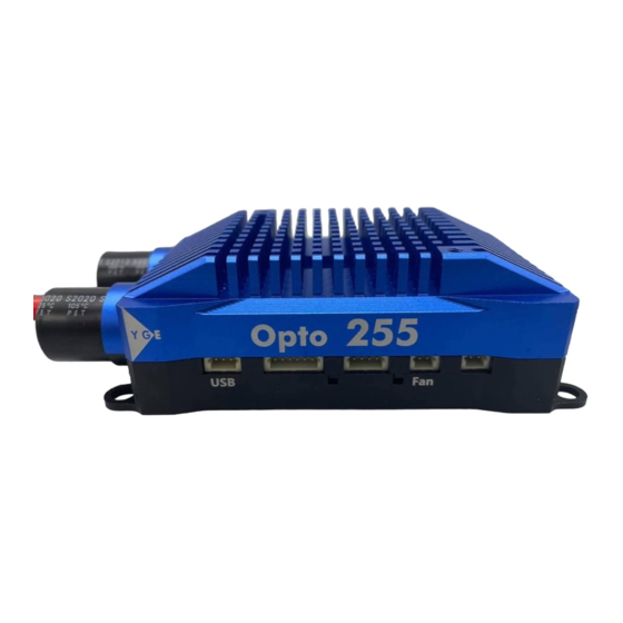
Speedcontroller YGE Opto 255
Technical data:
- Continuous current 255A (Full throttle). Max. acceleration
current 400A.
- Adjustable current limit up to 400A. The ESC won't shut
down, it will limit the current to 400A.
- 6 to 16s LiPo, max. terminal voltage 68V, nominal operating
voltage 63V.
- over 14S all-insulated and touch-proof connectors must be
used.
- pluggable receiver- and telemetry cables
- All signals are isolated by optocouplers for best noise
immunity.
- Electronic speed control (Governor- mode)
- Soft start
- Active free-wheel, allowing unlimited part load operation.
- Automatic or 6 step adjustable timing
- Frequency: Automatic.
- Adjustable EMK brake
- F3A(Acro brake (brake force control infinitely adjustable)
- Speed limit: 240.000 rpm (2- Poles)
- Temperature and overload warning
- Anti- flash: decreases the closing spark.
- Basic -Programming with mode programming
- Fine adjustment and selection of telemetry with the PC
Setup. Suitable USB-adapter optionally available
- Dimensions in mm: 119 x 54 x 31
- Weight with all cables: 365g
- Cable diameter battery / motor: 8² / 8²
We point out that the mode-setup has to be
successfully
done
controller!
For Navy please always choose mode 5.
It is also possible to set the half throttle way.
For LMT inrunners, the following settings are
Necessary:
Initial torque Normal
If you are using a Futaba transmitter, please
Set the framerate to 14ms (analog).
Start-up:
After connecting the main battery you will hear 3 descending
beeps. You need to connect the motor to hear the beeps;
whereby the connected motor acts as a beeper. A number of
beeps will follow according to the number of cells; a long beep
stands for 5 cells and a short beep for one cell.
Example: long...long...short...short - 5 + 5 + 1 + 1 =12 cells. If
the transmitter is now in the correct stop-position, you will hear
4 ascending beeps.
- The controller is now ready- .
If the motor turns in the wrong direction, it can be reversed by
exchanging 2 of the 3 motor wires.
Use only clean and tight gold connectors for the motor and
battery. The 5,5mm or 6mm gold-connectors have proven to
be the best choice. Exchange low-friction - or oxidized plugs
and sockets. Because only tight sitting contacts will ensure a
high current flow, protect the speed controller against
dangerous voltage peaks and avoid disturbances.
The entire wire length, from the controller to the battery, may
not exceed 30cm. If longer wires are necessary, more switch
resistant additional capacitors have to be used (Ultra Low
ESR). We recommend our capacitor module YGE Cap's 9.
Longer motor cables can be used. Twist the three cables in
order to minimise interference emission.
before
using
the
Attention:
Inverting battery polarity leads to severe damage and
loss of warranty!
Mode Programming:
1. For safety reasons remove ALL rotor blades!
2. Switch on the transmitter and move the throttle stick to
maximum (100%).
3. Connect the battery to the ESC → wait for the interval
beep:
♪♪♪ ... ♪♪♪ after 20 beeps the setup menu is
entered: confirmation ♪♪ .
4. Move the throttle stick to minimum and choose the
mode:
♪
Vbar - gov
♪♪
Gov - mode
♪♪♪
Gov - store
♪♪♪♪
Glider with folding propeller and brake
♪♪♪♪♪ Navy / Motor plane without brake
♪♪♪♪♪♪ Motor plane with F3A brake
5. At the desired mode, move the throttle stick to maximum:
confirmation ♪♪.
If no mode has been selected, the mode programming
starts again with mode 1 = Vbar - gov, etc....
6. Once a mode has been selected, move the throttle stick
to minimum: confirmation ♪♪.
You will hear the beeps acc to the number of cells and now
the
ESC
is
armed
- THE END -
PC-Software:
In the mode-programming, all parameters are set
automatically to useful values. We recommend to set as
less as possible in the PC-Software. Usually it is enough to
set the telemetry-settings, if necessary. For programming
with the PC-Tool, the optional USB-Adapter is necessary.
Please use the attached 3-pin telemetry-cable (Not the
Telemetry cable!) with the blue JR-plug for connecting the
ESC to the USB-adapter. More informations in the manual
of the USB-adapter.
ESC
Mode 1
Mode 2
Mode 3
Mode 4
Mode 5
Mode 6
and
ready
for
use.
Advertisement
Table of Contents

Related Manuals for YGE Opto 255


Summary of Contents for YGE Opto 255
- Page 1 30cm. If longer wires are necessary, more switch resistant additional capacitors have to be used (Ultra Low ESR). We recommend our capacitor module YGE Cap's 9. Longer motor cables can be used. Twist the three cables in order to minimise interference emission.
- Page 2 3 Beeps/flashes: Temperature rise warning 4 Beeps/flashes: Overcurrent YGE (preprogrammed): 5 Beeps/flashes: Receiver signals failed The YGE-protocol is for example for use with YGE TexY 6 Beeps/flashes: start up failed (Futaba, Spektrum, FrSky, Core), MSH Brain 2 or Spirit FBL.
Need help?
Do you have a question about the Opto 255 and is the answer not in the manual?
Questions and answers