Table of Contents
Advertisement
Quick Links
Technical data:
- The specified current is the maximum continuous full power current
- 2 to 6s LiPo, incl under voltage protection by power reduction
- Switching BEC
- Current limiting
- Disconnectable under voltage detection
- Electronic speed control (Governor- mode)
- Soft start
- Active free-wheel, allowing unlimited part load operation
- Automatic or 6 step adjustable timing
- Adjustable EMK brake
- F3A(Acro brake (brake force control infinitely adjustable)
- Frequency: 16 to 32 kHz
- Speed limit: 240.000 rpm (2- Poles)
- Temperature and overload warning
- Anti- flash: decreases the closing spark (starting from 65LVT)
- Basic -Programming with mode programming
- Fine adjustment and selection of telemetry log with the PC-Setup
- Suitable USB-adapter optionally available
Type
Bec 5,5...8,4V
Dimensions in mm
weight in g without / with cables
Cable-diameter battery / motor
We point out that the mode-setup has to be
successfully done before using the controller!
(By using VBC + NEO not necessary)
(Look at the back page)
Mode 1: V- Stabi - Gov (external Governor)
Plug the RPM-output of the blue 3-pin connector of the
controller into the rpm/ tele in-put of the receiver or FBL (for
wire assignment see additional page).
Make sure that the wire of the rpm signal is parallel to the
negative wire of the receiver wire.
Activate the rpm mode of your FBL system.
Mode 2: Standard Governor Mode
When operating in Gov mode, the ESC can be used
directly. If you want to fly different RPM's and switch them
in flight, you have to start with at least 70%. Then you can
switch over to different RPM's.
Mode 3: Gov.- Store
In Gov-Store you have to switch once to the highest
possible rpm after programming, ideally with 100% throttle,
in order to learn in the motor parameters. Thereafter you
can start with the lowest rpm and switch in flight if you
want.
Please read our detailed manual for the Gov.-store on our
webiste --> www.yge.de
The Gov. RPM regulator (Mode 2 and Mode 3) starts from
50% throttle opening. That is why we do not recommend to
operate the heli under 50%.
We recommend the following throttle openings:
Hover (Low RPM)
55 ... 60%
Standard
70%
3D
80 ... 85%
In case the headspeed is too high with the recommended
throttle openings, you should choose a lower pinion or a
motor with less kv.
.
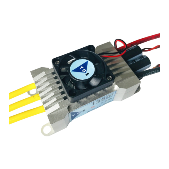
YGE 35LVT, 65LVT, 95LVT, 135LVT, 135 Slim
35A
5/10A
47 x 24 x 8
64 x 26 x 9
13 / 25
2,5² / 1,5²
2,5² / 2,5²
65A
95A
8/18A
8/18A
78 x 32 x 15
30 / 45
63 / 93
4² / 4²
Mode 4: Electronic gliders with brake
This mode includes all parameters for electronic gliders
with brake and outrunner motors.
Mode 5: Airplanes without brake
This mode contains all parameters for airplanes with
outrunner motors without brake.
Mode 6: Airplanes with Acro-brake (F3A brake)
This mode contains all parameters for airplanes with
outrunner- motors with Acro- brake for F3A competitions.
Start-up:
After connecting the main battery you will hear 3
descending beeps. You need to connect the motor to hear
the beeps; whereby the connected motor acts as a beeper.
A number of beeps will follow according to the number of
cells; a long beep stands for 5 cells and a short beep for
one cell.
Example: long...long...short...short - 5 + 5 + 1 + 1 =12 cells.
If the transmitter is now in the correct stop-position, you will
hear 4 ascending beeps.
- The controller is now ready- .
If the motor turns in the wrong direction, it can be reversed
by exchanging 2 of the 3 motor wires.
Use only clean and tight gold connectors for the motor and
battery. The 4mm / 5,5mm gold-connectors have proven to
be the best choice. Exchange low-friction - or oxidized
plugs and sockets. Because only tight sitting contacts will
ensure a high current flow, protect the speed controller
against dangerous voltage peaks and avoid disturbances.
The entire wire length, from the controller to the battery,
may not exceed 30cm. If longer wires are necessary, more
switch resistant additional capacitors have to be used (Ultra
Low ESR). We recommend our capacitor module YGE
Cap's 7. Longer motor cables can be used. Twist the three
cables in order to minimise interference emission.
135A
135 Slim
8/18A
8/18A
84 x 39 x 23,5
78 x 32 x 15
104/132
63/87
4² / 4²
4² 7 4²
Advertisement
Table of Contents

Related Manuals for YGE 135LVT


Summary of Contents for YGE 135LVT
- Page 1 YGE 35LVT, 65LVT, 95LVT, 135LVT, 135 Slim Technical data: - The specified current is the maximum continuous full power current - 2 to 6s LiPo, incl under voltage protection by power reduction - Switching BEC - Current limiting - Disconnectable under voltage detection...
- Page 2 Attention: BEC: Inverting battery polarity leads to severe damage and The BEC-Voltage can be adjusted in 0,1V steps in the PC- loss of warranty ! Software (optional USB-adapter available). It is possible to use a buffer-battery, no diodes are necessary. Caution! Make sure that the battery-voltage matches to the BEC- Mode Programming: voltage.
- Page 3 PC-Setup. The ESC has an Auto-Detect and sets all parameters by itself after startup. Also the telemetry will be automatically set to Mikado, so you can set all parameters in the transmitter. The YGE-App ..
Need help?
Do you have a question about the 135LVT and is the answer not in the manual?
Questions and answers