Table of Contents
Advertisement
Advertisement
Table of Contents

Related Manuals for Telex VEGA C-1616


Summary of Contents for Telex VEGA C-1616
- Page 1 Model C-1616 Radio Control Console Technical Manual August 2003 P.N. 803697...
-
Page 3: Table Of Contents
Remote Control Console Table of Contents 1 INTRODUCTION ..............................1 2 HARDWARE OVERVIEW.............................2 2.1 C-1616 C ..............................2 ONSOLE 2.1.1 Main PCB ..............................2 2.1.2 Keypad PCB..............................2 2.1.3 Line Card ..............................2 2.1.4 Internal Speaker Amplifier..........................2 3 CONTROLS AND INDICATORS ..........................3 3.1 F ...............................3 RONT ANEL 3.1.1... - Page 4 Vega’s C1616 6.2.2 Main Level Settings.............................15 6.2.2.1 Microphones Screen .............................. 15 6.2.2.1.1 Desk microphone Preamp Gain Screen ......................16 6.2.2.1.2 Handset Preamp Gain Screen ......................... 16 6.2.2.1.3 Aux Preamp Gain Screen ..........................16 6.2.2.2 Receive Path Levels............................... 16 6.2.2.2.1 Handset Earpiece Level..........................16 6.2.2.2.2 Aux Speaker Output Level ..........................
- Page 5 Remote Control Console 6.6.2 Function Tone Setup ...........................26 6.6.3 Frequency Programming Screen ........................26 6.6.4 Duration Display Screen ..........................26 6.7 U ..........................26 NSELECT ETUP PTIONS 6.7.1 Unselect Audio Routing ..........................26 6.7.2 Unselect Audio Mute...........................26 6.8 G ..........................26 ROUP ELECTION CREEN 6.9 S ............................27 UPERVISOR NABLE...
- Page 6 Vega’s C1616 Table of Figures Figure 1 Front Panel view..........................3 Figure 2 Rear Panel View ..........................5 Figure 3 Supervisory Diagram........................7 Figure 5 Line Card layout ..........................8 Figure 6 Crossmute Diagram .......................... 9...
-
Page 7: Introduction
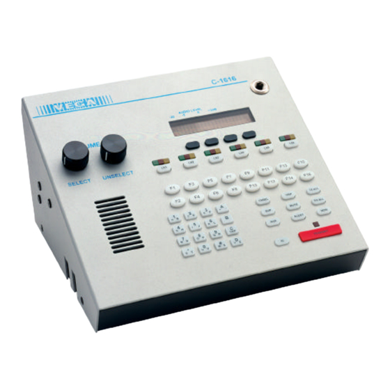
Remote Control Console 1 Introduction The model C-1616 is a unique multi-channel, multi-format, and self-contained desktop radio control console. The C-1616 sports a Vacuum Florescent LCD display, which provides channel alpha/numeric indication, clock and audio-level meter with a modern membrane keypad. These features allows for a more flexible dispatch environment in which the console may be installed. -
Page 8: Hardware Overview
Vega’s C1616 2 Hardware Overview The C-1616 is a multi-line; multi-mode console designed specifically for medium level system requirements. All functions are housed in a single small modern looking console. 2.1 C-1616 Console The C-1616 consists of the following sub-assemblies enclosed in the single case: Main Processing Board, Line Interface Cards, Keypad/Display Board, and speaker amplifier. -
Page 9: Controls And Indicators
Remote Control Console 3 Controls and Indicators 3.1 Front Panel Description of the controls and indicators. Line Audio Monitor Unselect Audio LED Select Audio LED Audio Level- +3dB 11:08AM Adam 12 Program 1-4 PROG 4 PROG 2 PROG 3 PROG 1 SELECT UNSELECT VOLUME Function Tone... - Page 10 Vega’s C1616 Optional Handset: When you come off hook the handset receive audio is transferred to the earpiece and the microphone mouthpiece becomes active. Unselect audio that is being routed to the external speaker will not be affected. VU Meter: Displays Selected receive and Microphone audio bus levels. This meter is shown on the top line of the display and utilizes the first 12 display elements from the upper left.
-
Page 11: Rear Panel Connections
Remote Control Console 3.2 Rear Panel Connections Line 1 Line 3 Line 5 Line 2 Line 4 Line 6 RELAY FOOT RECORD Power Power RS-232 AUX IN SWITCH SPEAK + GND E SW GND AUD PTT GND Figure 2 Rear Panel View 3.2.1 Rear Panel Ports Line Ports 1-6: The C-1616 can accommodate up to six-lines, in multiples of two. -
Page 12: Functional Description
Vega’s C1616 4 Functional Description 4.1 Grouping Options 4.1.1 Basic Line/Function Tone Operation The basic operating scenario would be a single line and function tone selected. Lines can be selected individually by pressing any LN1-LN6 and function tone button F1-F16. Upon keying the microphone, a high level guard tone followed the selected function tone is sent out, the low level guard tone is then transmitted along with the microphone audio. -
Page 13: Other Control Buttons
Remote Control Console 4.2 Other Control Buttons 4.2.1 Supervisor Button The SUP Button is used to disable all units on a particular Console 1: Console 2: Console 3: line. Its connection is similar to that of the crossmute function. Tech mode is utilized to determine which Line 1 Line 1 Line 1... -
Page 14: Line Card Setup And Description
Vega’s C1616 5 Line Card Setup and Description 5.1 INTRODUCTION/DEFAULTS The Line Card for the C-1616 system provides communication with any standard tone remote system. It is shipped from the factory in the following state: 4 Wire mode with 600 ohm Input and Output impedance 5.2 INPUT/OUTPUT 4 5 6 1) Cross Mute I/O... -
Page 15: Feature Description
Remote Control Console 5.3 FEATURE DESCRIPTION 5.3.1 Crossmute When a parallel console operator keys a microphone in the same room, the crossmute function will mute the receive audio path of other parallel consoles. This prevents any unwanted audio loops which would occur causing a loud squeal on the paralleled speakers. -
Page 16: Rx Side Settings
Vega’s C1616 5.3.3.1 RX Side Settings For 4-wire lines the RX side is jumper selectable for either 600 or 10k ohm impedance. If only one Line Card is on the line (no parallel consoles) then place J9 (Line 1,3,5) or J8 (Line 2,4,6) in the A position for a 600-ohm line impedance. -
Page 17: Transmit Level Setup
Remote Control Console 5.4.1.1 Transmit Level Setup The transmit level potentiometers are used to adjust the output levels of the transmit audio so that it is calibrated with the onscreen level sets found in the tech mode. Calibration of the Transmit lines will vary depending on system variables as well as the number of consoles found in parallel on the line. -
Page 18: Tech Mode
Vega’s C1616 6 Tech Mode The tech mode allows a technician to program the internal settings of the C-1616 console. MUTE - F6 - The tech mode is entered by pressing (star) simultaneously. The technician may be required to enter a PIN number to allow entry. See the section 6.3.4.1 on setting up the PIN number. The Opening Menu is displayed when tech mode is entered. -
Page 19: Opening Display Menu
Remote Control Console 6.0.3 Opening Display Menu |----------Level menu Screen |----------Line Level Settings (Select LEDS Blink) |----------RX Input Level |----------Other Line Levels |----------LAM Programming |----------LAM duration after release |----------Trigger Level |----------Select/Unselect Settings |----------Main Level Settings |----------Microphones |----------Desk microphone preamp gain |----------Handset preamp gain |----------Aux input preamp gain |----------Receive Path Levels... -
Page 20: Button Activated Setup Modes
Vega’s C1616 6.0.4 Button Activated Setup Modes |----------LN1-LN6 - Per Line Parameters Setup |----------Line Enable/Disable |----------Tone/Local Setting |----------Crossmute Enable/Disable |----------Squelch |----------TX Monitor Enable/Disable |----------AGC |----------TX Enable/Disable |----------Unselect Normal/Locked |----------F1-F16 - Function Tone Parameter Screen |----------Function Tone Enable/Disable |----------Tone Programming Screen |-----------Tone A/B Selection |-----------Frequency Programming Screen |-----------Duration Programming Screen... -
Page 21: Menu 1 - Line Level Settings
Remote Control Console 6.2.1 Menu 1 - Line Level Settings This screen is displayed after a line has been selected from the Level Menu Screen. The selected line number is shown on the display and the select LED for that line continues to blink. In this example Line 1 has been selected. PROG1 - Go to RX Input Level Screen Line 1 level adjust PROG2 - Go to LAM level setup... -
Page 22: Desk Microphone Preamp Gain Screen
Vega’s C1616 6.2.2.1.1 Desk microphone Preamp Gain Screen The current setting is shown in the upper right hand corner of the screen. This setting is for the pre-amp level of the deskmic. Deskmic level 45dB PROG1 - Resets level setting to default of +0dB back PROG2 - Increments the level setting by 1 dB (maximum of +10dB) PROG3 - Decrements the level setting by 1 dB (minimum of -10dB) -
Page 23: Tape Output Level
Remote Control Console 6.2.2.3.2 Tape Output Level The Tape output level is adjusted as shown on the display. The level will be dependent on the input level required by your recording equipment. PROG1 - Resets level setting to default of 0dBm Tapeout level PROG2 - Increments the level setting by 1 dBm (max of +10dBm) 0dBm... -
Page 24: Dump Error Screen
Vega’s C1616 6.3.2.1 Dump Error Screen This screen is displayed because an attempt to perform a memory dump was ended unsuccessfully for some reason. This stays up until the memory dump is aborted by pressing the “back” button or is attempted again by pressing the “Dump”... -
Page 25: Dtmf Tone Duration
Remote Control Console 6.3.3.1.1.2.1 DTMF Tone Duration This parameter determines how many milliseconds the DTMF tone of a prestored digit will last. The first number in the 100/100 represents the number of “on” milliseconds. DTMF Dur = 100 msec PROG1 - Resets duration setting to default of 100ms 100ms dwn back PROG2 - Decrements the duration setting by 10ms (min of 10ms) -
Page 26: Select Call Timer Duration Setup
Vega’s C1616 6.3.3.1.1.6 Select Call Timer Duration Setup The Unselect duration for incoming select call (see previous section for string and overall function setup information) is set in this screen. The default value is 7 seconds. This is the period of time for which the line will be unselected when the DTMF string is received. -
Page 27: Test Tone Screen
Remote Control Console Duration 130/200 PROG1 - Adjust Guard tone duration Guard Hold back PROG3 - Adjust Hold tone duration PROG4 - return to the Single Tone Settings Screen PROG1 PROG2 PROG3 PROG4 DTMF keypad (numbers only) - modify the settings 6.3.3.1.3 Test Tone Screen This screen allows the technician to control the tone generators on the console to facilitate testing. -
Page 28: Tx Delay Setup
Vega’s C1616 6.3.4.2 TX Delay Setup The C-1616 has the ability to delay transmit audio by up to 1 second. This allows an operator to begin speaking as soon as the microphone is keyed up. The radio system will have certain delays built in that under normal circumstances would not allow speech to be transmitted for a short period of time. -
Page 29: Alphanumeric Function-Line Setup
Remote Control Console 6.4 Alphanumeric Function-Line Setup This screen asks for the operator to choose a Line/Function tone combination or a Group to have an alphanumeric assignment or group alphanumeric assignment. While this screen is displayed, the keyboard blinks LN1-LN6, F1- F16, and GRP to remind the operator what buttons are used in this mode for programming. -
Page 30: Group Alphanumeric Selection Screen
Vega’s C1616 6.4.1.2.1 Group Alphanumeric Selection Screen Once the group has been selected the following screen is displayed. The top line displays the group number and the 8 digit alphanumeric that is displayed when the preprogrammed group is brought up in the operational mode. Group A Metro1 PROG2 - Enters the edit mode... -
Page 31: Squelch Setup
Remote Control Console 6.5.4 Squelch Setup The Squelch function can be turned on a per line basis. It is tied to the Line 3: Squelch ON level setup by the LAM function. If the LAM LED is blinking, squelch next back will not be active. -
Page 32: Function Tone Setup
Vega’s C1616 6.6.2 Function Tone Setup The top line of the display shows the function number, and whether the tone displayed is the A or B tone. Each function button can have up to two tones assigned to it which are sent out sequentially. The next item is the actual frequency of the function tone, followed by the duration of the tone in milliseconds. -
Page 33: Supervisor Enable
Remote Control Console 6.9 Supervisor Enable The supervisor function works in a manner similar to crossmute. It Super: Enabled allows a single console to take control of all selected lines by disabling prev next back transmit on all other attached consoles. See section 5 for information on the wiring required to support this function. -
Page 34: Cadence Level Selection
Vega’s C1616 6.12.1.1 Cadence Level Selection PROG1 - resets the level to the default of 0dBm Alert Lvl = PROG2 - decrements the level by 1 dBm back PROG3 - increments the level by 1 dBm PROG4 - return to the Alert setup menu PROG1 PROG2 PROG3... -
Page 35: Monitor Level
Remote Control Console PROG1 - resets the duration to the default value of 40ms Mon Dur = 40ms PROG2 - decrements the duration by 10ms (minimum of 40ms) 40ms back PROG3 - increments the duration by 10ms (maximum of 500ms) PROG4 - return to Monitor Characteristic Screen PROG1 PROG2... -
Page 36: Sample Setup Procedure
Vega’s C1616 7 Sample Setup Procedure The following example sets up the audio levels on both transmit and receive sides. 7.1 Transmit Path: The transmit path begins at the microphone of your choice and ends with the transmit line card jack. 7.1.1 Microphone adjustments There are two microphone inputs to the C-1616. -
Page 37: Transmit Monitor
7.4.6 Earth Ground While Telex-Vega recommends that the unit be tied to earth ground though the AUX power connector on the back of the unit, JP21 exist in the unit to allow the chassis ground to be tied to the signal ground of the unit. It is imperative that chassis ground to tied to some fixed reference for proper operation of the unit. -
Page 38: Theory Of Operation
Vega’s C1616 8 Theory of Operation The C-1616 is a Digital Signal Processor (DSP) based product. Because of this, many of the signals that once could be probed on older products, are handled within the DSP itself. This would include DTMF generators and decoders, notch filters, tone generators and decoders, and all of the audio summing. -
Page 39: Keypad/Display Board
Remote Control Console The receive path also has a tie in to the transmit path. One of the taps on the TX transformers (T3 and T4) is fed to an Op-Amp stage that is then summed into the receive path Op-Amp. Gain set Potentiometers (R57 and R58) can be adjusted to change the relative TX Monitor levels. -
Page 40: Line Card Installation
Vega’s C1616 9 Line Card Installation Installing and removing line cards can be completed in the field by qualified personnel. The steps for this process are listed below. 1) Remove power from the console. 2) Remove the four flathead screws holding the top of the case one. Two on each side. A phillips screw driver will be required. -
Page 41: Programming Chart
Remote Control Console 10 Programming Chart Section Parameter Default Programmed 6.3.4.1 PIN Number 5.3.3 Line 1 2 or 4 Wire mode 4 wire 5.3.3.1 Line 1 RX Impedance 600 ohms 5.3.3.2 Line 1 TX Impedance 600 ohms 6.2.1.1 Line 1 RX Input Level 0dbm 6.2.1.2.1 Line 1 LAM-S Release... - Page 42 Vega’s C1616 Section Parameter Default Programmed 5.3.3.2 Line 6 TX Impedance 600 ohms 6.2.1.1 Line 6 RX Input Level 0dbm 6.2.1.2.1 Line 6 LAM-S Release 7 seconds 6.2.1.2.2 Line 6 LAM-S Trigger Level -10dbm 6.2.1.2.1 Line 6 LAM-U Release 7 seconds 6.2.1.2.2 Line 6 LAM-U Trigger Level -10dbm...
- Page 43 Remote Control Console Section Parameter Default Programmed 6.4.1.1.1 Alphanumeric L1-F13 6.4.1.1.1 Alphanumeric L1-F14 6.4.1.1.1 Alphanumeric L1-F15 6.4.1.1.1 Alphanumeric L1-F16 6.4.1.1.1 Alphanumeric L2-F1 6.4.1.1.1 Alphanumeric L2-F2 6.4.1.1.1 Alphanumeric L2-F3 6.4.1.1.1 Alphanumeric L2-F4 6.4.1.1.1 Alphanumeric L2-F5 6.4.1.1.1 Alphanumeric L2-F6 6.4.1.1.1 Alphanumeric L2-F7 6.4.1.1.1 Alphanumeric L2-F8 6.4.1.1.1...
- Page 44 Vega’s C1616 Section Parameter Default Programmed 6.4.1.1.1 Alphanumeric L4-F11 6.4.1.1.1 Alphanumeric L4-F12 6.4.1.1.1 Alphanumeric L4-F13 6.4.1.1.1 Alphanumeric L4-F14 6.4.1.1.1 Alphanumeric L4-F15 6.4.1.1.1 Alphanumeric L4-F16 6.4.1.1.1 Alphanumeric L5-F1 6.4.1.1.1 Alphanumeric L5-F2 6.4.1.1.1 Alphanumeric L5-F3 6.4.1.1.1 Alphanumeric L5-F4 6.4.1.1.1 Alphanumeric L5-F5 6.4.1.1.1 Alphanumeric L5-F6 6.4.1.1.1 Alphanumeric L5-F7...
- Page 45 Remote Control Console Section Parameter Default Programmed 6.5.5 Line 1 TX Monitor 6.5.6 Line 1 RX AGC 6.5.7 Line 1 TX Enable Enabled 6.5.8 Line 1 Unselect Lock Unlocked 6.5.1 Line 2 Enable/Disable Enable 6.5.2 Line 2 Tone/Local Tone 6.5.3 Line 2 Crossmute 6.5.4 Line 2 Squelch...
- Page 46 Vega’s C1616 Section Parameter Default Programmed 6.6.4 F1-A Duration 40 msec 6.6.3 F1-B Frequency 6.6.4 F1-B Duration 40 msec 6.6.1 F2 Enable/Disable Enable 6.6.3 F2-A Frequency 1850HZ 6.6.4 F2-A Duration 40 msec 6.6.3 F2-B Frequency 6.6.4 F2-B Duration 40 msec 6.6.1 F3 Enable/Disable Enable...
- Page 47 Remote Control Console Section Parameter Default Programmed 6.6.3 F10-B Frequency 6.6.4 F10-B Duration 40 msec 6.7.1 Unselect Audio Route Internal 6.7.2 Unselect Audio Mute on PTT Not Muted Group A Lines 1 2 3 4 5 6 Group B Lines 1 2 3 4 5 6 Group C Lines 1 2 3 4 5 6 Group D...
-
Page 48: Schematics, Parts Placements, And Bills Of Material12 Warranty, Service, Repair, And Comments
Vega’s C1616 11 Schematics, Parts Placements, and Bills of Material... -
Page 49: Warranty, Service, Repair, And Comments
This drawing, written description or specification Is PART NO: Telex Communications INC. a proprietary product of TELEX, Lincoln, NE, and 879362 shall not be released, disclosed, nor duplicated without the written permission of TELEX. Lincoln, Nebraska USA APPROVALS: DR BY: DEE... - Page 50 This drawing, written description or specification Is PART NO: Telex Communications INC. a proprietary product of TELEX, Lincoln, NE, and 879362 shall not be released, disclosed, nor duplicated without the written permission of TELEX. Lincoln, Nebraska USA APPROVALS: DR BY: DEE...
- Page 51 This drawing, written description or specification Is PART NO: Telex Communications INC. a proprietary product of TELEX, Lincoln, NE, and 879362 shall not be released, disclosed, nor duplicated without the written permission of TELEX. Lincoln, Nebraska USA APPROVALS: DR BY: DEE...
- Page 52 This drawing, written description or specification Is PART NO: Telex Communications INC. a proprietary product of TELEX, Lincoln, NE, and 879362 shall not be released, disclosed, nor duplicated without the written permission of TELEX. Lincoln, Nebraska USA APPROVALS: DR BY: DEE...
- Page 54 STATUS This drawing, written description or specification RELEASED SBC SBC DEE 5/15/00 is a proprietary product of Telex, Lincoln, NE and shall not be released, disclosed, nor duplicated Q4 FROM NPN TO PNP. R30 & R49 TO 0 OHMS. 07-03-00 SBC SBC DEE 5/15/00 R56 TO 20K.
- Page 55 CHKR DATE STATUS This drawing, written description or specification RELEASED 5/15/00 is a proprietary product of Telex, Lincoln, NE and shall not be released, disclosed, nor duplicated without the written permission of TELEX. NOTES: REFERENCE PCB NUMBER : 750524 +10V +10V 0.1UF...
- Page 56 ECO NO. DRFT CHKR DATE STATUS This drawing, written description or specification is a proprietary product of Telex, Lincoln, NE RELEASED 5/15/00 and shall not be released, disclosed, nor duplicated without the written permission of TELEX. NOTES: REFERENCE PCB NUMBER :...
- Page 57 CHKR DATE STATUS This drawing, written description or specification RELEASED 5/15/00 is a proprietary product of Telex, Lincoln, NE and shall not be released, disclosed, nor duplicated without the written permission of TELEX. NOTES: REFERENCE PCB NUMBER : 750524 HSWITCH...
- Page 58 ECO NO. DRFT CHKR DATE STATUS This drawing, written description or specification is a proprietary product of Telex, Lincoln, NE RELEASED 5/15/00 and shall not be released, disclosed, nor duplicated without the written permission of TELEX. NOTES: REFERENCE PCB NUMBER : 750524 0.1UF...
- Page 59 This drawing, written description or specification Is PART NO: Telex Communications INC. a proprietary product of TELEX, Lincoln, NE, and 879682 shall not be released, disclosed, nor duplicated without the written permission of TELEX. Lincoln, Nebraska USA APPROVALS: DR BY: SBC...
- Page 60 This drawing, written description or specification Is PART NO: Telex Communications INC. a proprietary product of TELEX, Lincoln, NE, and 879682 shall not be released, disclosed, nor duplicated without the written permission of TELEX. Lincoln, Nebraska USA APPROVALS: DR BY: SBC...
- Page 62 CHKR DATE STATUS This drawing, written description or specification RELEASED 05/19/03 is a proprietary product of Telex, Lincoln, NE and shall not be released, disclosed, nor duplicated without the written permission of TELEX. NOTES: REFERENCE PCB NUMBER : 750640 +3.3V 0.1UF...
- Page 63 CHKR DATE STATUS This drawing, written description or specification RELEASED 5/19/03 is a proprietary product of Telex, Lincoln, NE and shall not be released, disclosed, nor duplicated without the written permission of TELEX. NOTES: REFERENCE PCB NUMBER : 750640 +10V +3.3V...
- Page 65 This drawing, written description or specification Is PART NO: Telex Communications INC. a proprietary product of TELEX, Lincoln, NE, and 879364 shall not be released, disclosed, nor duplicated without the written permission of TELEX. Lincoln, Nebraska USA APPROVALS: DR BY: DEE...
- Page 66 This drawing, written description or specification Is PART NO: Telex Communications INC. a proprietary product of TELEX, Lincoln, NE, and 879364 shall not be released, disclosed, nor duplicated without the written permission of TELEX. Lincoln, Nebraska USA APPROVALS: DR BY: DEE...
- Page 68 DATE STATUS This drawing, written description or specification RELEASED SBC DEE 5/15/00 is a proprietary product of Telex, Lincoln, NE and shall not be released, disclosed, nor duplicated R13,R16,R51 WERE 10K. R13,R16=18.2K; 05-86-00 05/31/00 R51=39.2K without the written permission of TELEX.
- Page 70 If such a malfunction occurs, the product will be repaired or replaced (at our option) without charge during the three-year period, if delivered to the Telex factory. Warranty does not extend to damage due to improper repairs, finish or appearance items, or malfunction due to abuse or operation under other than the specified conditions, nor does it extend to incidental or consequential damages.
- Page 72 13 Specifications Front panel controls Special features • ♦ Select and Unselect status for each line Automatic initial level settings • ♦ Sixteen Function tone button selection Self Tuning receive circuit • ♦ TX and RX ALL buttons Internal tuning via keypad •...
Need help?
Do you have a question about the VEGA C-1616 and is the answer not in the manual?
Questions and answers