Table of Contents
Advertisement
Quick Links
IP-1616/C-6200 Handset Option (Field Installation)
The IP-1616/C-6200 Handset Option allows the user to install a handset to the C-6200.
IP-1616/C-6200 Case Top
Observe the right side of the IP-1616/C-6200 case top to determine if there are handset mounting holes. Three black rubber plugs fill the
Handset Mounting Holes. Older units require mounting holes to be drilled. For more information, see "IP-1616/C-6200 Drilling Instructions" if
holes are required.
To remove the unit's case top, do the following:
Remove the screws attaching the top case to the unit.
1.
With the unit's left side facing forward, remove the top and place it to the right (back) of the unit.
2.
Remove the rubber plugs from the case top. See Figure 1.
3.
IP-1616/C-6200 Case Top with Rubber Plugs
FIGURE 1.
F01U275275 Rev. 01
1
09/2012
Advertisement
Table of Contents

Related Manuals for Telex IP-1616


Summary of Contents for Telex IP-1616
- Page 1 IP-1616/C-6200 Case Top Observe the right side of the IP-1616/C-6200 case top to determine if there are handset mounting holes. Three black rubber plugs fill the handset mounting holes. Older units require mounting holes to be drilled. For more information, see “IP-1616/C-6200 Drilling Instructions” if holes are required.
- Page 2 Lay out the Option Kit parts and compare with the assembly list to determine if all of the parts are present. See Figure 2. Option Kit Parts FIGURE 2. NOTE: When drilling holes, items 9, 10, and 12 are used to mount the Hanger Return Spring. (Item 13 is not used.) The Washer and Spacer both go on the inside of the case.
- Page 3 Insert the cable through the hole of the case top so the connector is on the inside of the case. See Figure 3. Inserting Cable through Case Top FIGURE 3. Solder one lead to pin #1. Solder the other lead to pin #3. See Figure 4. NOTE: Pin numbers are on the side of the switch.
- Page 4 Assemble the Snap Switch to the handset hanger using the 2-56 x 7/16” long screws and nuts so the switch button faces out. See Figure 5. Assembling Snap Switch to Handset Hanger FIGURE 5. After assembling the switch to the hanger, super glue the nuts to the switch housing. NOTE: Take care not to get glue on the screw threads.
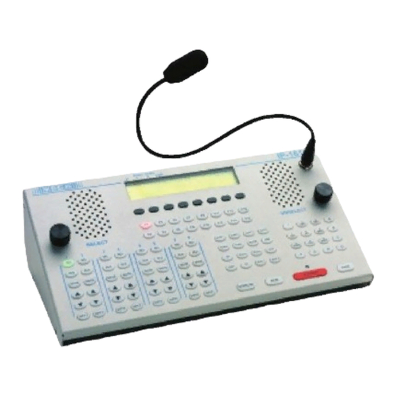
- Page 5 Secure the hanger to the standoff with the 5/8” long screws. See Figure 7. Securing Hanger to the Standoff FIGURE 7. Plug the switch cable connector into the PCBA. On the IP-1616, connect to J10. On the C6200, connect to J80. See Figure 8. IP-1616 and C6200 FIGURE 8.
- Page 6 IP-1616/C-6200 Drilling Instructions To drill handset mounting holes into the IP-1616/C-6200 case top, do the following: Remove the screws holding the case top to the unit and position the case top to allow the right side of the case to be drilled.
Need help?
Do you have a question about the IP-1616 and is the answer not in the manual?
Questions and answers