
Related Manuals for Weco 5K3-XP-EU

Summary of Contents for Weco 5K3-XP-EU
- Page 1 WECO 5K3-XP-EU Installation and User Manual WECO 5K3-XP-EU AUSTRALIA VERSION LOW VOLTAGE...
- Page 2 WECO 5K3-XP-EU ATTENTION: The battery could explode and/or be severely damaged if dropped or crushed. ATTENTION: Appropriate mechanical lifting equipment must be used since the Battery Module weighs 126.3Lbs / 57.3 kg ATTENTION: The battery may explode if exposed to open flames or other extreme sources of heat.
-
Page 3: Table Of Contents
WECO 5K3-XP-EU Contents Statement ............................6 Preface............................. 6 Declaration ............................6 System Design ......................7 Battery Operation ..........................7 Storage ................................7 Temperature ..............................7 Depth of Discharge (DoD) ..........................7 Charging ................................7 Warranty ................................7 Product Overview ..........................7 Symbols Used .......................... - Page 4 WECO 5K3-XP-EU 1.4 Battery Terminal Function Definition ......................25 1.5 Out of the Box Pre-Operational Check ......................25 SECTION 2 - LOW VOLTAGE CONFIGURATION ..................27 2.1 Product Introduction ..........................27 2.1.1 Identifying the Individual Module ........................... 27 2.1.2 Accessory List (Standard Kit 120A Single Module LV) ........................29 2.1.3...
- Page 5 WECO 5K3-XP-EU 2.10.1 Single Cluster Configuration Kit ............................58 2.10.2 Multi Cluster Hub Device ..............................58 2.11 Low Voltage Inverter Battery to Inverter CAN Terminal Pin Out …………………………………………………….59 SECTION 3 WECO BMS - LOW VOLTAGE PC SOFTWARE for 5K3-XP-EU ..........62...
-
Page 6: Statement
WECO 5K3-XP-EU Statement: The information and guidance contained in this manual is related to the WECO Stackable model Section 2 is for LOW VOLTAGE APPLICATION of battery. This manual contains In case of product upgrades or other reasons, this document will be adjusted accordingly. Unless otherwise... -
Page 7: System Design
Any other use, even if permitted by the BMS ranges, is not covered by the Performance Warranty. Product Overview The WeCo 5K3-XP-EU is a Stackable Battery Module with a DUAL VOLTAGE module that can be used in a Low Voltage... -
Page 8: Symbols Used
Make sure to use the correct inverter charging parameters before connecting to the battery. Each WeCo 5K3-XP-EU Battery Module has two different circuits and depending on the inverter voltage range, the installer must choose the correct battery configuration for that range. -
Page 9: Battery Module Overview
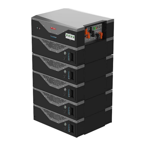
WECO 5K3-XP-EU Battery Module Overview INFORMATION provides tips that are valuable for optimum installation and operation of the product. POWER OPERATOR PORT RUN BUTTON SWITCH CONNECTION HUB PROTECTION PLATE UPPER REMOVABLE BRACKET WALL BRACKET LOWER REMOVABLE BRACKET REMOVABLE HANDLES STRUCTURAL FEET... - Page 10 WECO 5K3-XP-EU ATTENTION: THE BATTERY IS DUAL VOLTAGE – IT CAN BE INSTALLED IN A LOW VOLTAGE CONFIGURATION. BE AWARE OF THE DIFFERENT CONNECTION METHODS AND THE SPECIFIC USE OF THE TERMINAL CONNECTORS. LOW VOLTAGE ONLY SCREW TERMINAL LOW VOLTAGE...
- Page 11 WECO 5K3-XP-EU...
-
Page 12: Safety Warnings And Notifications
All electrical connections on the WeCo 5K3-XP-EU Battery Module shall be made only by qualified personnel. When installed and operated in accordance with this manual, the WeCo 5K3-XP-EU Battery Module will perform in a safe and reliable manner in accordance with the battery operating specifications. -
Page 13: Warning Statements
WECO 5K3-XP-EU Warning Statements Lithium Iron Phosphate (LiFEP04) Battery or Cell DANGER Hazard Statement The materials contained in this product may only represent a hazard if the integrity of the cell or battery is compromised; physically, thermally, or electrically abused. The below are the hazards anticipated under those conditions: Causes skin irritation. Causes serious eye irritation. -
Page 14: General Preparation
Before starting any operation on the battery, make sure to position the modules in their final position and structurally fix all the modules that make up the system. WeCo 5K3-XP-EU Battery Modules can be installed by wall mounting vertically or stacking horizontally. - Page 15 WECO 5K3-XP-EU ATTENTION: STACKABLE INSTALLATION INFORMATION The stack configuration shall be concluded by interlocking the modules by using the module feet as shown below: Use the two screws to fix the feet across the modules The screw holes are on...
- Page 16 STACKABLE MODE CABLES PASSAGE ATTENTION: The WeCo 5K3-XP-EU Battery Module has two terminals for connecting the power The installer must pay the utmost atte s n u ti p o p n ly t . o the respective functions. LOW VOLTAGE...
-
Page 17: Section 1 - Storage & Pre-Operational Procedures
WECO 5K3-XP-EU SECTION 1 - STORAGE & PRE-OPERATIONAL PROCEDURES 1.1 Storage - Transportation – Removing / Relocation of Batteries ✓ This Battery is considered DANGEROUS GOODS by the United Nations and must be treated accordingly. ✓ Each box comes from the factory with the below labels: ✓... - Page 18 LOW VOLTAGE LV HUB Each device or accessory of the 5K3-XP-EU will have a specific Firmware that manages the logic and interconnection functions between Battery Modules and devices. It is therefore important to understand the operational and interaction concepts of the 5K3-XP-EU battery within a more complex system.
-
Page 19: Module Unpacking And Handling
WECO 5K3-XP-EU Module Unpacking and Handling The battery is always delivered in WALL mode, and it is therefore necessary for the installer to make simple changes to install the STACK kit. Below are the installation phases. ATTENTION: The battery must be lifted by four persons, using the four handles. -
Page 20: Package Information And System Configuration List
Refer to Section 2.1.3 for Low Voltage packing list. If battery is damaged and/or components missing, contact your local WeCo representative. NOTE: The WeCo 5K3-XP-EU Battery Module ships as standard in the wall mount configuration. 1.3.1 Battery Dimensions* (Wall Bracket) - Page 21 WECO 5K3-XP-EU ATTENTION: The Battery Module weighs 126.3 lb (57.3 kg) and must be installed with the help of a mechanical lift, and/or with at least two people equipped with suitable suction cups for mechanical lifting or lifting straps. STEP 1A 100/120 cm suggested height The Bracket must be installed on a flat and vertical wall.
- Page 22 WECO 5K3-XP-EU Step 2A: In case of multiple module installation, make sure to respect the distance between the modules and the ceiling. Min 30 cm 25 cm 25 cm 25 cm 25 cm 25 cm Example of a Floor or Wall Mounted battery cluster connected with power cables and data cables.
- Page 23 WECO 5K3-XP-EU Examples of a Floor or Wall Mounted battery cluster. Cable routing behind the battery Remove the rubber Secure the battery to feet starting from the wall using the the 2 module standard bracket upward Leave the rubber feet of...
-
Page 24: Stack Mount
The Battery Module weighs 126.3 lb /57.3 kg and must be installed with the help of a mechanical lift, and/or with at least two people equipped with suitable suction cups for mechanical lifting or lifting straps. As previously stated in this manual, the 5K3-XP-EU Battery Module comes as standard in wall mount Stackable configuration. - Page 25 WECO 5K3-XP-EU Before stacking the batteries, the installer must check the maximum permissible floor load. It is recommended that the installer obtains approval from a civil engineer. For vertical ground mounting, the support surface of the Battery Module is distributed on 4 insulated supports (rubber pads), 10 x 4 cm each.
-
Page 26: Battery Terminal Function Definition
WECO 5K3-XP-EU 1.4 Battery Terminal Function Definition The terminal layout is shown in the following figure: Battery Terminal Wiring Definition Table Interface Name Function LV POLE + LOW VOLTAGE POSITIVE (+) Screw Terminal LV POLE - LOW VOLTAGE NEGATIVE (-) Screw Terminal... - Page 27 If the LED bar is all illuminated in RED, there is a major fault and you should not attempt any further operation of the battery. Contact WeCo support at info@wecobatteries.ae. There is an RS232 Operator Port which will allow you to check all parameters of the Battery Module. Full instructions on how to interface to the RS232 port can be found in this manual.
-
Page 28: Section 2 - Low Voltage Configuration
2.1 Product Introduction The WeCo 5K3-XP-EU Battery Modules can be used as an on-grid or off-grid energy storage system. It is not recommended to use this product for any purpose other than the intended purpose as described in this document. - Page 29 The nameplate label describes the product parameters and is attached to the product. For details, please refer to the nameplate label of the product. For safety reasons, the installer must have a thorough understanding of the contents of this manual before installing the product. WeCo BATTERY MODULE – PRODUCT LABEL...
-
Page 30: Accessory List (Standard Kit 120A Single Module Lv)
WECO 5K3-XP-EU 2.1.2 Accessory List (Standard Kit 120A Single Module LV) The Battery Module is packed in a carton together with standard accessories. When unpacking the Battery Module, be sure to check that the Battery Module and accessories are free from damage and that the correct quantities of each component are included within the carton. -
Page 31: Necessary Installation Tools
WECO 5K3-XP-EU 2.1.3 Necessary Installation Tools Insulated Allen Key Set from 2 mm Drill + Hammer Insulated Screwdriver Set Multimeter + Current clamp to 8 mm RS232/USB + Screw Terminal (insulated) Electrician Scissors Insulated Torque Wrench Set Lifting Strap + Mechanical Lifter... -
Page 32: Low Voltage Module Wiring And Set Up
CAUTION : The LV fuse is contained in the left portion of the Battery Module as shown above. The access to the fuse is restricted to authorized WeCo service personnel and the protection lid cannot be opened by anyone else. -
Page 33: Low Voltage Dip Switch Settings
All drawings are for reference only. Always refer to the physical product as the standard. If the manual does not match the physical product, stop all actions, remove any connections, and store the batteries in a safe place. Call your WeCo technical service representative for assistance. -
Page 34: Low Voltage Parallel Configuration
WECO 5K3-XP-EU 2.3.1 LOW VOLTAGE PARALLEL CONFIGURATION The DIP switch must be set as follows to allow a single Battery Module to communicate with an inverter using CAN communications: WHEN THE INVERTER HAS A CANBUS COMMUNICATION PORT, SWITCH #7 OF THE MASTER BATTERY MUST ALWAYS BE SET TO “ON.”... -
Page 35: Module Activation And Shutdown
WECO 5K3-XP-EU Module Activation and Shutdown START UP PROCEDURE The Power Switch and Run Button are located to the right of the battery terminal connections on the side of the battery chassis. The Power Switch is a mechanical switch that switches the battery ON or OFF. The Run Button is an LED button that is only enabled when the Power Switch is in the ON (1) position. -
Page 36: Low Voltage Parallel Set Up Overview
All drawings are for reference only. Always refer to the physical product as the standard. If the manual does not match the physical product, stop all actions, remove any connections, and store the batteries in a safe place. Call your WeCo technical service representative for assistance. -
Page 37: Auto Id Assignment And Dip Configuration For Low Voltage Single Cluster (Parallel Connection)
WECO 5K3-XP-EU DIP SWITCH TO BE SET 00000000 WHEN THE BATTERY IS OFF CAN to Inverter To start up the system just press the Master Run Button CAN PORT 2A MASTER Port RS485B Port RS485A SUB 1 Port RS485B Port RS485A... - Page 38 WECO 5K3-XP-EU STEP 2 AUTO WAKE-UP PROCESS (Pressing the RUN BUTTON ) Once all the connections have been checked, it is possible to start the Battery Module by enabling the automatic wake-up process. Press the RUN button of the MASTER battery, the RUN BUTTON will Blink and will wake-up all the SUB batteries connected.
-
Page 39: Single Cluster Dip And Data Connection
WECO 5K3-XP-EU 2.5.2 Single Cluster DIP and DATA Connection The DIP SWITCH setting for the SINGLE CLUSTER LV mode has an automatic function that assigns the single module ID in cascade. It is mandatory to connect each module in Daisy Chain connection starting from the RS485B PORT of the master unit. -
Page 40: Parallel Battery Wiring Connections
All drawings are for reference only. Always refer to the physical product as the standard. If the manual does not match the physical product, stop all actions, remove any connections, store the batteries in a safe place and call your WeCo technical representative for assistance. Attention: For the power cable connection for high current, please refer to the specific section to see the diagram. - Page 41 WECO 5K3-XP-EU following the installation sequences and guidelines as described in Section 1 and Section 2 of this manual. Connect the power cables as indicated below, making sure that the batteries are OFF (check the button LED on the ZERO VOLTS.
- Page 42 Illustrations shown are for reference only. Please always refer to the physical Battery Module in front of you, and if the module has a different configuration to this manual, stop all activity immediately and contact your WeCo technical service representative.
-
Page 43: Led Bar Indications
WECO 5K3-XP-EU 2.5.5 LED Bar Indications LED Bar is located just above the RUN BUTTON and the BMS SWITCH Start Up : LED1-LED5: Green 5 seconds Running : il LED1-LED5 become blue and the SOC level is displayed SOC 90-100%... -
Page 44: Stand Alone Battery Front Panel Control
WECO 5K3-XP-EU 2.6 Stand Alone Battery Front Panel Control 2.6.1 Start Battery Turn on any circuit breakers between battery and inverters. Press the Run Button for 2-seconds. The GREEN RUN light should come on. The Battery Module has been activated normally. -
Page 45: Shutdown Of Parallel Batteries
WECO 5K3-XP-EU 2.7.2 Shutdown of Parallel Batteries Press and hold the Master Run Button for 5-seconds. The GREEN RUN light should go off immediately. The GREEN RUN lights on the sub batteries will not be extinguished immediately. The RED FAULT lights on the sub batteries’ FRONT LED bars will start flashing after ten seconds and the GREEN RUN lights will remain on. -
Page 46: Direct Parallel Connection With Certified Inverter Bms Communication (Closed-Loop)
Note that for installations WITH certified Inverter BMS Communications the maximum number of battery modules per installation is limited to five clusters of eight batteries per cluster. The 5K3-XP-EU Low Voltage Hub must be used when the installation has more than one cluster. -
Page 47: Power Connection Of A Single Cluster
WECO 5K3-XP-EU 2.8 Power Connection of a Single Cluster -Double BUS BAR- ATTENTION: Both ends of the cluster must be connected with two output cables 50 mm2. Cables length shall not exceed 250cm. The suggested output cable is composed of two sets of 50 mm2 each. - Page 48 WECO 5K3-XP-EU Cable size verification for a cluster composed by 5 or more Battery Modules connected to the inverter with 2 sets of cables (50mm² each) for a total of 100 mm² each terminal (positive and negative). Numbers of Modules...
-
Page 49: Can Hub For Multi Cluster Configuration
SET THE INVERTER POWER AS PER THE CABLES’ CAPABILITIES Each battery pack and each cluster must have the same Voltage and Firmware. All stack configurations must use the WeCo Bus Bar. Each cluster must have the same number of battery packs. - Page 50 WECO 5K3-XP-EU The 5K3-XP-EU HUB can manage a maximum of 7 clusters composed of a maximum of 15 modules each. A MULTI CLUSTER SYSTEM SHALL BE CONNECTED WITH BUS BAR BETWEEN MODULES. Interface Description and Connector I/O CONTACT 2X Programmable closure/contact...
-
Page 51: Low Voltage Can Hub Dimensions
WECO 5K3-XP-EU 2.9.1 Low Voltage CAN HUB Dimensions Kg: 8 Weight: 2.9.2 Control Logic and Protection Limit The inverter, if applicable, must be set with the below restrictions in addition to the BMS control logic. MAX CURRENT WITH BUS BAR... -
Page 52: Can Hub General System Description
2.9.3 CAN Hub General System Description CAN Hub is Mandatory for Multiple Cluster Installation ATTENTION: BEFORE PROCEEDING WITH THE 5K3-XP-EU INSTALLATION IT IS MANDATORY TO READ THE INSTRUCTIONS BELOW Special BUS Bar for Parallel Configuration (MODULES INTERCONECTION BUS BAR MODEL – ACCESSORY* ``WeCo LV BUS BAR -300A``) -
Page 53: Master Id Set Up And Connection Diagram
WECO 5K3-XP-EU Before using the MASTER HUB device, make sure to update the modules with the latest update Firmware available on www.wecobatteries.ae. To use and set up the MASTER HUB, the installer must follow the instructions contained in this manual. - Page 54 WECO 5K3-XP-EU It is important to follow the diagrams below to make the connections in the correct sequence. Each cluster must have its own unique address which will be assigned by the first battery of each cluster. All the batteries in the group except the first must have the DIP switches set to 00000000 (see picture):...
-
Page 55: Power Connection Example
WECO 5K3-XP-EU 2.9.6 Power Connection Example Communication Diagram + Power Connection CAN INPUT FROM LAST CLUSTER Master Inverter PARALLEL BUS TWO POLES BREAKER NEGATIVE POWER CABLES CLUSTER 2X50/75mm² CLUSTER ID02 ID01 GROUND CABLES 10mm² RS485 PARALLEL RJ45 Cable DATA COMM GROUND CABLES 10mm²... -
Page 56: Conceptual Diagram Of A Cluster Composed By 5 Clusters And 8 Batteries Each
2.9.7 Conceptual Diagram of a Cluster composed of 5 clusters of 8 batteries each. - Page 58 WECO 5K3-XP-EU Note: It is possible to install up to 7 clusters composed of 15 batteries each for a total of 105 batteries. CAN BMS SUB n SUB 1 MASTER IF A CIRCUIT BREAKER IS INSTALLED POWER LINE MAX 60Vdc...
-
Page 59: Conceptual Diagram Between Master Modules Of Multiple Clusters
WECO 5K3-XP-EU 2.9.8 Conceptual Diagram between Master Modules of multiple clusters. Note: It is possible to Install up to 7 clusters composed of 15 batteries each for a total of 105 batteries. ATTENTION The Last module of the cluster must have the DIP 6 ON in order to enable the 120 Ohm Terminator... -
Page 60: Single Cluster Configuration Kit
WECO 5K3-XP-EU 2.10.1 Single Cluster Configuration Kit 5K3-XP-EU STANDARD LV BUS BAR 300A KIT 1 x Custom BUS BAR Insulated RED module connection Each kit includes 1 x Custom BUS BAR Insulated BLACK module connection 1 red + 1 black... - Page 61 WECO 5K3-XP-EU...
-
Page 62: Low Voltage Inverter Battery To Inverter Can Terminal Pin Out
WECO 5K3-XP-EU 2.11 Low Voltage Inverter Battery to Inverter CAN Terminal Pin Out Inverter Invertr Side Battery Side CAN TERMINAL Terminal Type (PIN Number) (PIN Number) CAN L CAN H SMA SUNNY ISLAND RJ45 CAN L ZCS HYD/SP CAN H... - Page 63 WECO 5K3-XP-EU HIGH VOLTAGE CONFIGURATION(Please contact WECO) ATTENTION: The 5K3-XP-EU may be connected in a high voltage configuration. Contact manufacturer/importer/distributor (WECO) for more details.
-
Page 64: Section 3 Weco Bms - Low Voltage Pc Software For 5K3-Xp-Eu
RS232 Serial Converter with 232-RJ45 Plug WeCo Monitor PC-SOFTWARE PIN OUT RS232 CONVERTER STEP 1 Download the latest version of the WeCo BMS PC software at www.wecobatteries.ae Enter the password: 1010 Click: Operator Access to run the program in -Operator Mode-... - Page 65 STEP 3 Connect the RJ45 plug from the RS232-USB Converter to the Operator Port of the Battery Module. Operator Port is located on the battery side, near the RUN button. nd PRESS RUN Turn On The PLUG OPERATOR PORT RS232 POWER SWITCH BUTTON 2 sec STEP 4 Select the COM PORT from the PC Software.
- Page 66 STEP 5 When the communication is established between the PC and the Battery Module, the PC software will display a page like the one below: If more than one battery is connected in parallel, all the information will be displayed on this page. These pages will automatically update for up to 15 modules.
- Page 67 STEP 7 FIRMWARE UPGRADE To update the firmware to a more recent version, it is necessary to download the latest version of the WeCo BMS software www.wecobatteries.ae and install it from the software as indicated.
- Page 68 MOBILE Bluetooth APP Install the WEC App by downloading it from the App Store / Google Play Search For: WeCo WiFi To get the Remote Monitoring APP Search For: WeCo Bluetooth To get the Local APP MOBILE APP GENERAL OVERVIEW + FIRMWARE UPGRADE...
- Page 69 Operator Access Enable the Blueetoth Password 1010 is required for function Private User To Change Protocol press here Running Alarms or Warns will appear here Software upgrade...
- Page 70 ATTENTION, BATTERY ALARMS/WARNS In the presence of any alarm / warns on both the battery and the inverter, the user must switch off and disconnect the power connection between the batteries and the inverter. The battery must be inspected immediately with an authorized WeCo technician or Send the battery to WeCo for an accurate check.
- Page 71 WeCo srl Viale Kennedy 113-121 Scarperia Firenze Italia www.wecobatteries.com All data subject to change without notice. Actual product color may vary. No part of this document can be copied r reproduced, electronically or mechanically, without written permission from the company...
Need help?
Do you have a question about the 5K3-XP-EU and is the answer not in the manual?
Questions and answers