Advertisement
Quick Links
ORDER NO. EMID0007014C0
A5
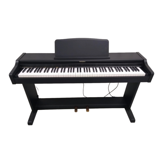
Digital Piano
SX-PC25
Colour
(K) ...................Black
Areas
(P) U.S.A. Mexico
(PC) Canada
(EX) Norway, Sweden, Denmark, Finland, Spain, Portugal, Greece,
South Africa
(EZ) Germany
(EG) Switzerland, France, Italy, Austria, Netherlands, Belgium
(EB) the United Kingdom
(XA) Argentina
(XD) Hong Kong, Saudi Arabia, Kuwait
(XT) Taiwan
(XS) Malaysia, Singapore
(X) Thailand, Indnesia, Iran, U.A.E., Panama, Brasil, Philippines,
Venezuela, Ecuador, Colombia, Chile, Peru
(GN) Australia, New Zealand
1
Advertisement

Related Manuals for Technics SX-PC25


Summary of Contents for Technics SX-PC25
- Page 1 ORDER NO. EMID0007014C0 Digital Piano SX-PC25 Colour (K) ....Black Areas (P) U.S.A. Mexico (PC) Canada (EX) Norway, Sweden, Denmark, Finland, Spain, Portugal, Greece, South Africa (EZ) Germany (EG) Switzerland, France, Italy, Austria, Netherlands, Belgium (EB) the United Kingdom (XA) Argentina...
- Page 2 SPECIFICATIONS SPECIFICATIONS KEYBOARD 88 KEYS (WITH TOUCH RESPONSE) SOUND GENERATOR MAX. POLYPHONY 32 NOTES (16 STEREO NOTES) SOUND GRAND, UPRIGHT, E PIANO, HARPSI, STRINGS, PIPE ORGAN PEDAL SOFT, SUSTAIN DIGITAL REVERB FUNCTIONS VOLUME, DEMO, TUNING, TRANSPOSE, TOUCH SENSITIVITY, REVERB, BASIC CHANNEL, LOCAL CONTROL TERMINALS PHONES ×...
-
Page 3: Safety Precaution
cabinet, or on the part concerned. Please follow these safety precautions, and also those listed in the Owner'sManual. 2. Parts which have a ; mark in the circuit diagram or in the parts list are essential for safety. When replacing these parts, be sure to useonly the specified parts. - Page 4 4. After servicing, be sure to restore the lead dress, insulation barriers, insulation papers, shields, etc. 5. Before returning the serviced equipment to the customer, be sure to make the following insulation resistance test to prevent the customer from being exposed to a shock hazard. 2.2.
-
Page 5: Parts Location
6. Parts Location 7. Disassembly Instructions 7.1. Removing the top cover and the keyboard cover [Fig. 1]... - Page 6 (Step2) Remove the top cover in the direction of arrows (refer to [Fig. 1] (Step3) Remove the keyboard cover in the direction of arrow (refer to [Fig. 1] 7.2. Removing the keyboard assembly - Follow the item 7.1. [Fig. 2] 7.3.
- Page 7 7.3.2. Assembly (Step1) Insert the front part of the key into the chassis. (Step2) Insert the plate spring into the hammer notch (refer to [Fig. 4] (Step3) While slowly lowering the key into the chassis, insert the plate spring into the notch at the rear of the key (refer to [Fig.
- Page 8 7.4. Disassembly of the pedal assembly (Step1) Remove the pedal assembly from the pedal box. (Step2) Disassemble the pedal assembly (refer to [Fig. 5] [Fig. 5] 7.5. Removing the printed circuit boards - Follow the item 7.1. - Pull out the connectors on the printed circuit boards. - ACP P.C.B.
-
Page 9: Symptoms Which Appear To Be Signs Of Trouble
(Step2) Remove the screw (refer to [Fig. 6] - MAIN P.C.B. (Step1) Remove the screw (refer to [Fig. 6] (Step2) Release the claws of the 5 P.C.B. holders. - HPVOL P.C.B. (Step1) Remove the 2 screws (refer to [Fig. 6] (Step2) Remove the volume knob. -
Page 10: Precautions Before Servicing
The following changes in performance may occur in the Technics Digital Ensemble but do not indicate trouble. Phenomenon Remedy No sound is produced when the keyboard is No sound is produced if the MAIN VOLUME is set played. Use the sliding control to set the volume to an appropriate level. - Page 11 Oscilloscope VP-5730A”. Therefore the waveforms of musical tone signals shown may differ somewhat due to the difference in the timing of triggering. 2. Since the 1/10 test probe is used, the indicated voltage value on the bottom part of each waveform illustration is 1/10 of the actual value (e.g.
-
Page 12: Specification
SPECIFICATION SYMBOL Fixed Carbon Film Resistors “FLAME-PROOF” (ERD—F—type) Fixed Wire Wound Resistors “FLAME-PROOF” (ERF—type) Fixed Metal Oxide Film Resistors “FLAME-PROOF” (ERG—type) Fixed Metal Film Resistors “FLAME-PROOF” (ERX—type) Fixed Metal Film Resistors (Precision and High Stability) (ERO—type) Fuse Type Fixed Metal Oxide Film Resistors “FLAME-PROOF”... -
Page 13: Measuring Condition
SPECIFICATION TYPE SYMBOL Non-Polarized Electrolytic ECEA_KN_type Capacitors Non-Polarized Electrolytic (for ECEA_Y_type Network system) Tantalum Solid Electrolytic ECS_type Capacitors Metalized Plastic Film ECQV_type Capacitors (TF Series) Temperature Compensating ECC_type Ceramic Capacitors High-Dielecytric Constant ECK_type Ceramic Capacitors ECR_type Axial Lead Ceramic Capacitors ECB_type Metalized Polyester Film ECQ_EW_type Capacitors for Across the Line... - Page 14 12. Schematic Diagram 13. Printed Circuit Board Diagram 14. Block Diagram 15. Wiring Connection Diagram 16. Replacement Parts List Notes:...
- Page 15 *Important safety notice: / Components identified by mark have special characteristics important for safety. / Funrthermore, special parts which have purposes of fire-retardant (resistors), high-quality sound (capacitors),low-noise (resistors), etc. are used. / When replacing any of components, be sure to use only manufacture’s specified parts shown in the parts list. *Capacity values are in microfarads (uF) unless specified otherwise, P=Pico-farads (pF) F=Farads (F) / *Resistance values are in ohms, unless specified otherwise, 1K=1,000 (OHM), 1M=1,000K (OHM)
- Page 16 Ref. No. Part No. Part Name & Description Remarks QGKG0159AA ORNAMENT [SPC] QMFG1276AA FELT [SPC] QMFG1067AA FELT [SPC] K2AA2G000003 AC INLET COVER (X,XA,EX,EZ,EB,EG,EF,XD) [SPC] K2AA2G000003 AC INLET COVER (XT,XS,GN,EG,XD) [SPC] SJS9334A AC IN SOKET (P,PC) [SPC] QQLG147AA HEADPHONE LABEL [SPC] QLZG021A CORE (P,PC) [SPC]...
- Page 17 Ref. No. Part No. Part Name & Description Remarks 18-4 QMRG7031EC PROTECTOR [SPC] 18-5 QMRG7032EC PROTECTOR [SPC] 18-6 QGKG0135AA ORNAMENT [SPC] 18-7 XTB3+6A SCREW [SPC] QMFG1026AA FELT [SPC] QKQGP029AAZK LEFT PLANK ASS'Y [SPC] SHRG9620A CRAMPER [SPC] QKQGD101AA CROSSBOARD [SPC] QKQGP030AAZK RIGHT PLANK ASS'Y [SPC] SNEG1760A...
- Page 18 Ref. No. Part No. Part Name & Description Remarks QMWG6021AA RUBBER SWITCH [SPC] QMWG6020AA RUBBER SWITCH [SPC] QMWG8038AA HAMMER SUPPORT(WHITE KEY) [SPC] QMWG8039AA HAMMER SUPPORT(BLACK KEY) [SPC] QMWG8040AA FUL CU RUM(12 PCS,ON ONE) [SPC] QMWG8041AA FUL CU RUM(4 PCS,ON ONE) [SPC] QMWG8045AA KEY GUIDE...
- Page 19 Ref. No. Part No. Part Name & Description Remarks ECRR1H104ZF 50V 0.1P HPVOL [SPC] ECKCVA1472MF 4.7U ACP [SPC] ECRF1H104ZF 25V 0.1U MKB2 [SPC] ECUV1H471JG 50V 470P MAIN [SPC] ECQU2A104MN 250V 0.1U ACP [SPC] ECRF1H104ZF 25V 0.1U MKB2 [SPC] C6,C7 ECUV1H104ZFX 50V 0.1U MAIN [SPC] ECUV1H104ZFX...
- Page 20 Ref. No. Part No. Part Name & Description Remarks ECEA1CKA100 16V 10 MAIN [SPC] C92,93 ECUV1H104ZFX 50V 0.1U MAIN [SPC] C95-100 ECUV1H104ZFX 50V 0.1U MAIN [SPC] C101,02 ECEA1HKA010 50V 1U MAIN [SPC] C103,04 ECQV1H104JM 50V 0.1U MAIN [SPC] C105,06 ECUV1H102JX 50V 0.01U MAIN [SPC] C107...
- Page 21 Ref. No. Part No. Part Name & Description Remarks MA8033H DIODE MAIN [SPC] MA111TX DIODE MAIN [SPC] MA165 DIODE MKB1 [SPC] MA111TX DIODE MAIN [SPC] MA165 DIODE MKB1 [SPC] EK04W DIODE MAIN [SPC] D16,17 MA165 DIODE MKB1 [SPC] MA8051L DIODE MAIN [SPC] D18-25 MA165...
- Page 22 PCB3 SXPG235541A ACP P.C.B. (RTL) [SPC]...
- Page 23 Ref. No. Part No. Part Name & Description Remarks PCB4 SXPG235311 MAIN P.C.B. (RTL) [SPC] PCB5 SXPG218231 PKB P.C.B. (RTL) [SPC] PCB6 SXPG231111A MKB1 P.C.B. (RTL) [SPC] PCB7 SXPG231111B MKB2 P.C.B. (RTL) [SPC] PCB8 SXPG235511A ACP P.C.B. (RTL)(X,XS,XT,XD,XA) [SPC] PCB8 SXPG235521A ACP P.C.B.
- Page 24 Ref. No. Part No. Part Name & Description Remarks ERJ6GEYJ681V 1/10W 680 MAIN [SPC] ERJ6GEYJ101V 1/10W 100 MAIN [SPC] ERJ6GEYJ222V 1/10W 2.2K MAIN [SPC] ERJ6GEYJ103V 1/10W 10K MAIN [SPC] ERJ6GEYJ221V 1/10W 220 MAIN [SPC] ERJ6GEY0R00V 1/10W 0 MAIN [SPC] ERJ6GEYJ105V 1/10W 1M MAIN [SPC] ERJ6GEYJ103V...
-
Page 25: Cabinet Parts Location
Ref. No. Part No. Part Name & Description Remarks RJ1-3 ERDS2T0 1/4W 0 PKB [SPC] QSPG1010AA SW,POWER [SPC] S1-3 QSTGT001AA LEVER SWITCH PKB [SPC] SP1,2 QASG12P07A 12CM SP [SPC] EVQ21507K SW,TACT SW [SPC] QSRGT005AA VOLTAGE SELECTOR ACP [SPC] EVQ21507K SW,TACT SW [SPC] QTPG1M059A POWER TRANSFORMER... - Page 27 18. Manual Keyboard Parts Location...
- Page 28 19. Packaging...
- Page 29 Printed in Japan / H000700000 KA/HH...
- Page 31 SCHEMATIC DIAGRAM-1 NOTE: The number which noted at the connectors on the schematic diagram as "SCHEMATIC DIAGRAM-1" or "SCHEMATIC DIAGRAM-2" indicates the schematic diagram serial number located on the left corner in the schematic diagram. ACP CIRCUIT MAIN CIRCUIT PRODUCTS FOR POWER TRANSFORMER QSRGT005AA...
- Page 32 SCHEMATIC DIAGRAM-2 MIDI OUT IC13 M5F7805L +3.3D (+5V REGULATOR) 2SB709 130uHx3 MA2062LF MA111 MA111 2SD601 2SB709 0.1P 0.1P MA111 100K 0.1P MA8033HTX 0.1P 16V330 220P VOPM VOPS 2SA1015 0.1P 100P 25V1000 0.1P EK04W 0.1P PMUT 2SD601 4.7K 0.1P 2.2K 16V220 2SC1815 0.1P C125...
- Page 33 SCHEMATIC DIAGRAM-3 MIDI IN 130uHx3 0.1P 64 63 62 61 60 59 58 57 56 55 54 53 52 51 50 49 48 47 46 45 44 43 42 41 0.1P MA111 VREFH T93CU44F1B VREFL (MAIN CPU) 0.1P 0.1P AVSS QCPL-260L AVCC (PHOTO COUPLER)
- Page 34 SCHEMATIC DIAGRAM-4 +3.3D 11.28MHz NRSTSG RAMDT2 NRSTCPU RAMDT4 RAMDT3 SDIREV SDOREV SDICH0 SDOCH0 SDIDRY SDODRY TEMODE3 TEMODE2 DIVOUT SDOMIX LRCK ROMDT11 ROMDT4 D97315GD201 (DIGITAL SIGNAL PROCESSOR) ROMDT3 ROMDT12 ROMDT10 ROMDT5 ROMDT2 ROMDT13 ROMDT9 ROMDT6 INTOUT ROMDT1 RXBUSY MCKIN ROMDT14 ROMDT8 TEMODE0 ROMDT7 TEMODE1...
- Page 35 SCHEMATIC DIAGRAM-5 IC10 0.1P QSIGX3C32003 (32M BIT DYNAMIC RAM) 0.1P R54 +3.3D VCC BYTE 4 5 6 220x4 LRCK ML/IIS DATA MC/DM1 MD/DM0 CLK0 MUTE MODE CS/IWO DGND 0.1P ZERO 0.1P 10 AD VCC2R VCC2L AGND2R AGND2L 0.1P EXTR EXTL 16V10 16V10 VOUTR...
- Page 36 SCHEMATIC DIAGRAM-6 +3.3D C108 0.1P 4.7Kx4 +3.3D +3.3D 4.7Kx4 MA111 MA111 220x4 MA111 MA111 MA111 MA111 220x4 MA111 MA111 220x4 C110 C112 C117 100P 100P 100P C111 C116 100P 100P HPVOL CIRCUIT ERG1SJ100E HEADPHONE1 0.047 0.047 ERG1SJ100E 130uHx3 ERG1SJ100E ERG1SJ100E HEADPHONE2 PMUTE HVOL...
- Page 37 SCHEMATIC DIAGRAM-7 MKB1 CIRCUIT HD74LS138P +VCC (3 TO 8 DECODER) 6.3V47 UNLESS OTHERWISE SPECIFIED: DIODES ARE MA165.
- Page 38 SCHEMATIC DIAGRAM-8...
- Page 39 SCHEMATIC DIAGRAM-9 MKB2 CIRCUIT UNLESS OTHERWISE SPECIFIED: DIODES ARE MA165.
- Page 40 SCHEMATIC DIAGRAM-10 HD74LS138P (3 TO 8 DECODER) +VCC...
- Page 41 SCHEMATIC DIAGRAM-11 HD74LS138P (3 TO 8 DECODER) +VCC...
- Page 42 SCHEMATIC DIAGRAM-12...
- Page 43 MAIN P.C.B. (COMPONENT SIDE) RESET +LOUT -LOUT IC13 C108 40 41 C109 C107 +ROUT -ROUT C104 C72 C70 C103 R102 Q11 Q12 R103 C106 D3 D2 C102 C88 C73 C71 C68 R104 R100 C101 5 4 6 (SXPG235311) ELECTRICAL PARTS LOCATION Ref.No.
- Page 44 MAIN P.C.B. (FOIL SIDE) C119 R20 Q3 C123 C118 C122 C116 C112 C110 C117 C100 C125 R105 R76 R75 IC10 R101 R61 R55 C105 (SXPG235311) ELECTRICAL PARTS LOCATION Ref.No. Lo.No. Ref.No. Lo.No. Ref.No. Lo.No. Ref.No. Lo.No. Ref.No. Lo.No. Ref.No. Lo.No. MAIN P.C.B.
- Page 45 MKB1 P.C.B. D72 D70 SW40 SW38 SW32 SW30 SW29 SW28 SW27 SW26 SW25 SW24 SW23 SW43 SW42 SW41 SW39 SW37 SW36 SW35 SW34 SW33 SW31 SW44 D25 J6 SW19 SW18 SW15 SW22 SW21 SW20 SW17 SW16 SW14 SW13 SW12 SW11 SW10 (SXPG231111A) ELECTRICAL PARTS LOCATION...
- Page 46 MKB2 P.C.B. D142 D140 D138 D136 D134 D176 D174 D172 D170 D168 D166 D164 D162 J17 D160 D158 D156 D154 D152 D150 D148 D146 D144 D167 D165 D163 D159 D157 D155 D151 D149 D147 D145 D139 D137 D135 D133 D175 D173 D171 D169...
- Page 47 SW P.C.B. (SXPG235411) ELECTRICAL PARTS LOCATION Ref.No. Lo.No. Ref.No. Lo.No. SW P.C.B. HP VOL P.C.B. CN2 R5 (SXPG235511B) ELECTRICAL PARTS LOCATION Ref.No. Lo.No. Ref.No. Lo.No. Ref.No. Lo.No. Ref.No. Lo.No. Ref.No. Lo.No. HPVOL P.C.B.
- Page 48 ACP P.C.B. OTHERS (SXPG235511A) (SXPG235541A) ELECTRICAL PARTS LOCATION Ref.No. Lo.No. Ref.No. Lo.No. ACP P.C.B. (SXPG235521A)
- Page 49 PKB P.C.B. JR1 JR3 SUSTAIN SOSUTENUTO SOFT (SXPG218231) ELECTRICAL PARTS LOCATION Ref.No. Lo.No. Ref.No. Lo.No. Ref.No. Lo.No. Ref.No. Lo.No. PKB P.C.B.
- Page 50 Tone Signal MAIN Control Signal D2,D3 POWER RESET TRANSFORMER POWER SWITCH D4 D7 AC CORD IC13 REGULATOR Q4,Q5 +3.3V +3.3D REGULATOR Q11,Q12 RESET RA0-RA19 SD0MIX CONVERTER IC10 RESET DIGITAL RA0-RA19 Q9,Q10 SIGNAL 32M BIT PROCESSER DYNAMIC RD0-RD15 RD0-RD15 RESET A1-A4 ADDRESS BUS A1-A4 P57(AN7)
- Page 51 HPVOL AUX IN R-CH AUX IN L-CH MAIN VOLUME HEADPHONE2 HEADPHONE1 IC6,7 POWER 12cm; 4 AMPLIFIER POWER INDICATOR 12cm; 4 PEDAL IN SOFT SOSUTENUTO SUSTAIN MIDI OUT PHOTO MIDI IN COUPLER SOUND MODE MKB1 MKB2 DECODER SWITCHES DECODER DECODER & DIODES SWITCHES &...
- Page 52 W5QEXGVH04070F PKB P.C.B. BLACK BLACK WHITE W1 QJLG013AA 12cm, 4 12cm, 4 ACP P.C.B. MAIN P.C.B. PEDAL IN POWER TRANSFORMER W2 QEXGVH030708 POWER SWITCH AC POWER CORD HPVOL P.C.B. CORE MKB1 P.C.B. MKB2 P.C.B. QEXGSS16022C QEXGSS16022C...
- Page 53 Follow the steps below to assemble your Technics piano. Make sure you are using the correct parts and that they are in the correct direction. • At least 2 people are required for assembly. • To disassemble the piano, reverse the procedure.
- Page 54 Pedals Plug the power cord into the wall socket. Install the music stand (included). • Insert it into the two holes. Soft pedal Sustain pedal Open the keyboard cover. Sustain pedal • Open and close the cover gently. The sound fades gradually after the keys are released. Turn on the POWER button.
- Page 55 ⇒ While pressing the MODE SET button, press ⇒ While pressing the MODE SET button, press the keyboard key that corresponds to the the keyboard key that corresponds to REVERB desired TOUCH SENSITIVITY (LIGHT/ NOR- OFF or ON. • When the MODE SET button is pressed, its indicator MAL/HEAVY).
Need help?
Do you have a question about the SX-PC25 and is the answer not in the manual?
Questions and answers
How to reset the SX PC25 Technics piano to its original settings?